Are ball valves ok to use on return lines?

If you have a properly sized pump a simple valve is all you need. The little bit of extra restriction is not going to matter. If the pump is significantly oversized a bypass line is better, mostly due to getting enough flow though the pump to cool it adequately. If you need to use a bypass line then you should look at getting a smaller pump, unless you are keeping the reserve capacity for future use.

I believe this is the best answer for the original poster's question.

I personally learned a lot! :bigeyes:
 
It's a bit frustrating when I post a suggestion and someone (in this case Wazzel) says NOPE, might as well said hey dummy you don't know what you're talking about. I'm not going to respond to more of his posts. I will try to respond to yours, so you have a little more information or another point of view.

This link is a bit deep, but, does a pretty good job of explaining the dynamics of multiple different water pump technology.
http://www.pumped101.com/efficiency.pdf

Take note that it's very general, but, the pumps used in our tanks are not FREQ drive (VHD), meaning that their RPM is derived from utility power 60hz, the impeller design is usually optimized at about 6' some less some more. So, when you use a ball valve it artificially increases head pressure (often beyond optimal design), and therefore reduces the pump life and will ALWAYS use more energy.

I will agree there may be some pump manufacturers that do a poor job of QC and would allow a free-flowing pump to overspend causing damage, but, I would hope this would be the exception not the rule.

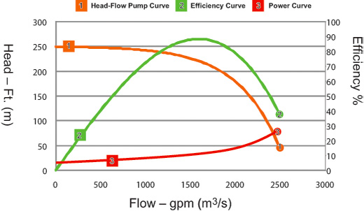
If you reference the article or most any pump manufacturer's flow graph, you will see a sweet spot (peak efficiency). Again in aquariums, this I have found to be about 4-6 ' where there is some loss of flow, but, substantially less than 50%. This matches the typical PEAK EFFICIENCY of a pumps design. So.... If you need 60 or 70% of the capacity of the pump to meet your needs, and you add a ball valve, you push the envelope of low efficiency. Much like any machine, they are designed to run at a higher capacity than required, but, they use more energy, create more heat and therefore don't last as long.

The above said, the opposite is true, if the design is for 4-6 ' and you run it at 1' flow will be maxed out with LESS actual work being done and a different pump would be a better choice. Damage, maybe on cheap bearings, irregular windings, things of generally poor quality equipment.

So... Look at our user Mag 700, let's assume 5' HP
https://www.google.com/search?q=mag...aquarium+pump+700+curve&imgrc=QkJFJWhYJPFKzM:

He has max about 400gph, which means 100% capacity, if you reference the 1st link, you will see efficiency is the worst at this rate, so why restrict it to 300gph and hold that bottom of the curve, relieve the pressure back to the sump, move left of the power curve, draw less wattage, make less heat and get the same results.

Now... If his goal was 100gph, you would already be to the left of the EFFICIENCY curve and additional pressure may (I still have trouble with this, because it has to ASSUME bad quality parts) allow the pump to last longer. Now even with a concession of it lasting longer, it will still (likely based on constant speed which is known and impeller design which is unknown) take more ENERGY (watt hours) to push 200gph than 100gph to 5'. It may be very minor, but, I promise unless the impeller has SEVERE cavitation the energy will be more.

Hope this helps get a different scientific explanation on why a simple restrictor on a semi-reasonably sized pump, is not better than a relief.


Sent from my iPad using Tapatalk

I said nope, because what you said was incorrect. Centrifugal pumps decrease power usage with decreased flow. To get to the point where decreasing flow increases power usage you need to get to axial flow (propeller) pump. It is just the nature of the designs.

The information you provided in this post is also incorrect. If you just want to argue and be right I will leave you alone after this. If you want to learn something I will be more than happy to offer explanations. I do not think you are a dummy, but you do look to be misinformed.
 
I think the best advice is don't get a grossly oversized pump. Either way you do it you will be using more electricity and producing more heat than one that is properly sized.
 
Hence why I'm buying a smaller pump right now :(

I recently found that 'Free' does not always mean 'best' :-D
 
I said nope, because what you said was incorrect. Centrifugal pumps decrease power usage with decreased flow. To get to the point where decreasing flow increases power usage you need to get to axial flow (propeller) pump. It is just the nature of the designs.


The information you provided in this post is also incorrect. If you just want to argue and be right I will leave you alone after this. If you want to learn something I will be more than happy to offer explanations. I do not think you are a dummy, but you do look to be misinformed.


I have provided documentation, you have provided statements. XKZERO courtesy of Marv's reef has provided photos, you keep rambling\. Why?


Sent from my iPad using Tapatalk
 
I have provided documentation, you have provided statements. XKZERO courtesy of Marv's reef has provided photos, you keep rambling\. Why?


Sent from my iPad using Tapatalk

Here is a typical centrifugal pump cure that shows that pump power increases with flow not pressure. I posted a similar one but you ignored it. This alone disproves that throttling down a pump always uses more power. Quite the opposite actually.

PumpCurve1-11.jpg


You might want to check this out to improve you pump cure reading skills.

http://www.nesc.wvu.edu/pdf/dw/publications/ontap/tech_brief/tb55_pumpcurves.pdf

The fact that the efficiey of the pump changes over the operating range is not due to poor quality parts, but due to the hydrodynamics in the impeller and volute.

The BEP for a pump is similar (see Fig. 3). With the discharge valve closed (“dead head”) and zero flow, efficiency is zero. As the discharge valve opens (i.e., the discharge restriction is gradually reduced), flow and efficiency gradually increase, until the flow through the pump becomes more turbulent. At that point, efficiency will start dropping and then continue to drop as the pump approaches “run out” condition (zero). As with traffic flow on a busy highway, somewhere between “dead head” and “run out” condition, there is a flow rate at which the efficiency is maximum—i.e., the BEP.

http://www.maintenancetechnology.com/2013/05/the-importance-of-best-efficiency-point-bep/

Pipes in parallel have equal losses. To use a by pass line you have to create losses equal to those in the line going to the tank. Lift + flow losses. Using a by pass line does not change the pressure the pump sees. That is a simple hydraulic principal.

As far as pump efficiency I have yet to see a manufacturer of aquarium equipment supply that publicly, so if you have source for that please provide.

From reeflow.
4. If your pump is producing too much flow, you can reduce the flow by partially closing a
valve on the discharge line. Never restrict the inlet!!! Surprisingly, this will make the motor work
less and use less electricity!!

http://users.neo.myregisteredsite.com/0/1/3/11915310/assets/tips.pdf
 
Here is a typical centrifugal pump cure that shows that pump power increases with flow not pressure. I posted a similar one but you ignored it. This alone disproves that throttling down a pump always uses more power. Quite the opposite actually.


PumpCurve1-11.jpg


You might want to check this out to improve you pump cure reading skills.


http://www.nesc.wvu.edu/pdf/dw/publications/ontap/tech_brief/tb55_pumpcurves.pdf


The fact that the efficiey of the pump changes over the operating range is not due to poor quality parts, but due to the hydrodynamics in the impeller and volute.


http://www.maintenancetechnology.com/2013/05/the-importance-of-best-efficiency-point-bep/


Pipes in parallel have equal losses. To use a by pass line you have to create losses equal to those in the line going to the tank. Lift + flow losses. Using a by pass line does not change the pressure the pump sees. That is a simple hydraulic principal.


As far as pump efficiency I have yet to see a manufacturer of aquarium equipment supply that publicly, so if you have source for that please provide.


From reeflow.


http://users.neo.myregisteredsite.com/0/1/3/11915310/assets/tips.pdf


Have you ever put a watt meter on a pump? I seriously doubt it. Look at the power curve, more flow, more head pressure, more X power goes up, no freewheel. But... You can't let it go because you know everything.


Sent from my iPad using Tapatalk
 
Have you ever put a watt meter on a pump? I seriously doubt it. Look at the power curve, more flow, more head pressure, more X power goes up, no freewheel. But... You can't let it go because you know everything.


Sent from my iPad using Tapatalk

You asked for data, I provided. I have tested pumps for a living, so yes I have taken power measurements on pumps.

Flow and pressure are inversely related on a pump cure. Power goes up as flow increases and pressure goes down. It is right there on the curve. If you can not get that right I do not know where to go with you.

Contrary to what you think I am doing, I am only trying to give good information. My experience in this area is better than hobbyist level.
 
You asked for data, I provided. I have tested pumps for a living, so yes I have taken power measurements on pumps.


Flow and pressure are inversely related on a pump cure. Power goes up as flow increases and pressure goes down. It is right there on the curve. If you can not get that right I do not know where to go with you.


Contrary to what you think I am doing, I am only trying to give good information. My experience in this area is better than hobbyist level.


I get it if I get 500gph at 5psi or 10psi it's the same power. At least per your theory.


Sent from my iPhone using Tapatalk
 
I get it if I get 500gph at 5psi or 10psi it's the same power. At least per your theory.


Sent from my iPhone using Tapatalk

If it is the same pump you will not have different pressures at the same flow rate. It is just not possible, centrifugal pumps do not function like that.
 
Let's move along folks. Clearly a difference of opinion but the one thing I think everyone agrees on is that the pump is too big. ;)
 
If it is the same pump you will not have different pressures at the same flow rate. It is just not possible, centrifugal pumps do not function like that.


Right which is why restricting the pump (pressure) results in less flow but the same energy. Look at a flow chart every centrifugal pump has max HP almost zero flow this is also peak power


Sent from my iPhone using Tapatalk
 
Right which is why restricting the pump (pressure) results in less flow but the same energy. Look at a flow chart every centrifugal pump has max HP almost zero flow this is also peak power


Sent from my iPhone using Tapatalk

If you have max power at 0 head it is not a centrifugal pump. Centrifugal pump have a characteristic increasing power with flow curve. That is not something I made up. Here is a chart that should the various typic curve for various pumps.

Figure-2-PE0312.jpg
 
If you have max power at 0 head it is not a centrifugal pump. Centrifugal pump have a characteristic increasing power with flow curve. That is not something I made up. Here is a chart that should the various typic curve for various pumps.

Figure-2-PE0312.jpg
What 3 pumps are those for?

Sent from my VS987 using Tapatalk
 
What 3 pumps are those for?

Sent from my VS987 using Tapatalk

Those are typical pump curves for various families of pumps. Not for any pump in particular. The one to the far left is for radial flow pumps, generally high pressure low flow. The center one is for Francis vein/ mixed flow pumps. Those are medium head, medium pressure. Those one to the right is for axial flow/propeller pumps which are high flow low head pumps.
 
I haven't read the entire thread but someone posted about using a kill-a-watt meter to test this out. I used a syncra 7 and ball valve on the output. As I closed the valve the wattage lowered. Checked with an amp meter and it agreed. The more restrictive the flow the less amps pulled.
 
Back
Top