tkeracer619
New member
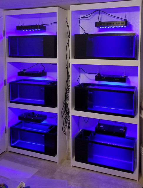
I am not normally one who cheaps out on dosing pumps. I have about $10k retail value of masterflex hardware in my setup but I ran into a situation that required I have 6 ATO setups. My typical setup is an AutoTopOff.com float switch and a masterflex peristaltic but that was going to be cost prohibitive for this particular project. I decided to modify a pair of Jebao DP-4 dosing pumps to accept float switches. This thread should give you the info you need to do this yourself. I am linking the items I bought but have no monetary or incentives from the sellers to do so. They simply have the specs we need and are cheep.
I'm sure there are other ways to do this but I feel like this is a cheap and reliable way to create a bunch of Auto Top Off systems for those folks who need several setups or for someone who needs an ATO and has a spare channel on their dosing pump, Modifying only one channel would allow you to use it as an ATO.
Hope this is helpful to someone . Enjoy!
Supplies needed...
Jebao DP-4 Dosing Pump (others hobbby pumps will probably work in a similar manner)
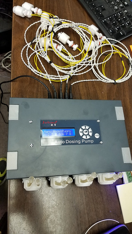
Float Switches
Connectors - Plugs and Sockets
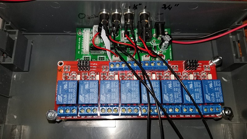
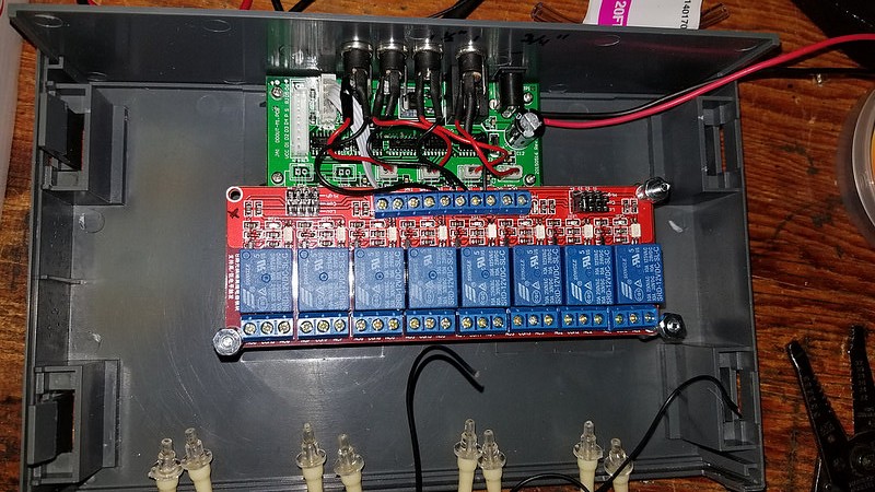
Relay Board
Marine Grade Heat Shrink Tubing
Various size heat shrink tubing.
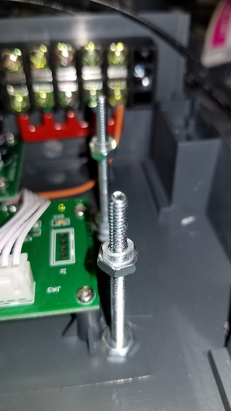
6-32 Button Head Screws 2" Long and an extra pack of nuts.
Wire ~22ga
Screwdrivers
Wire Strippers
Soldering Iron - Use a good one
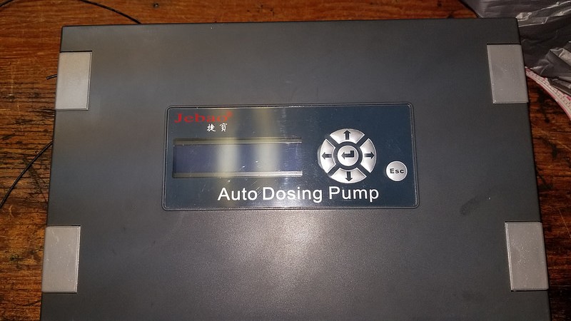
In case you aren't sure, this is the one we are talking about. It's a 4 head pump. I purchased mine via international snail mail for about $55ea. Make sure it functions before taking it apart!
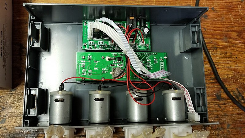
First step is to open up the case. The silver tabs on the front slide up towards you if you are looking at the screen, this gives you access to the clips. Prod in here with a slotted screwdriver. Take care not to drop the pump assembly when taking the case apart. It is best to do this with the screen facing the ground and removing the back of the case from the front.
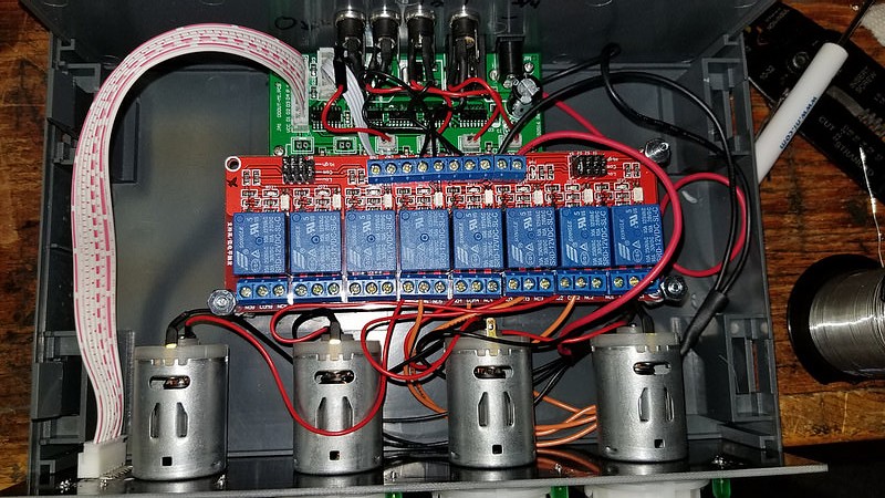
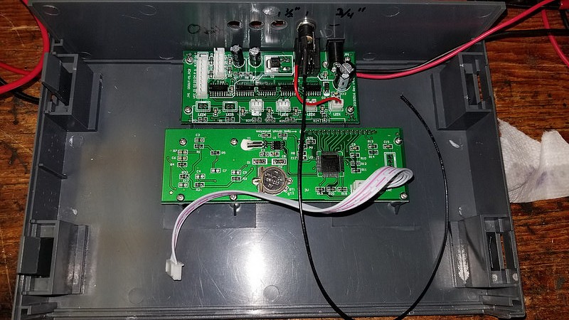
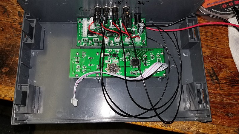
Once open with the screen facing a bench, this is what we have. Go ahead and unplug all of the cables and remove the pump assembly, set it aside. Remove the 4 Phillips screws that hold the logic board, we will mod it in the next step (pictured at the top)
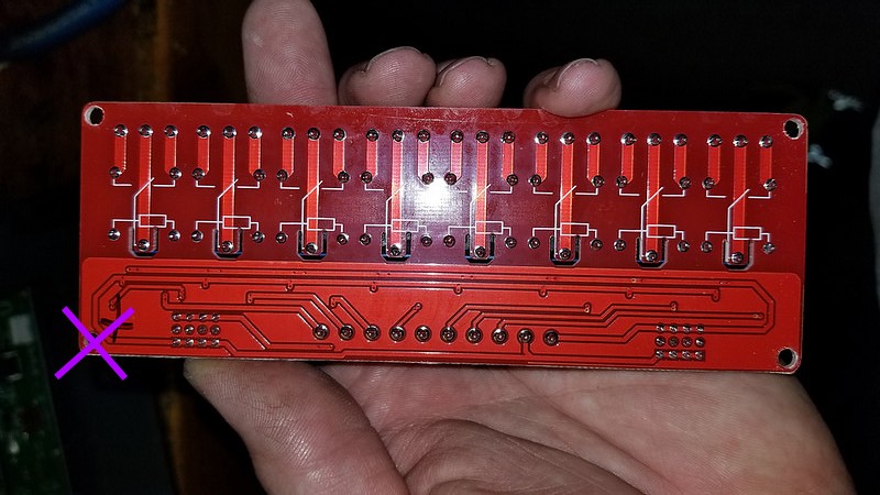
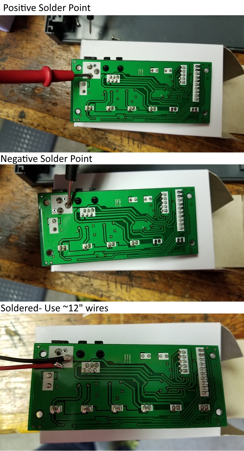
We need to tap into the 12v power supply to drive our relay board. On the back of the logic board solder two wires to the shown solder joints. Take care not to overheat the board. Use 12" wires here, they will be cut to length at a later time. Note polarity and be sure you can identify which is positive and negative once the board is in place.
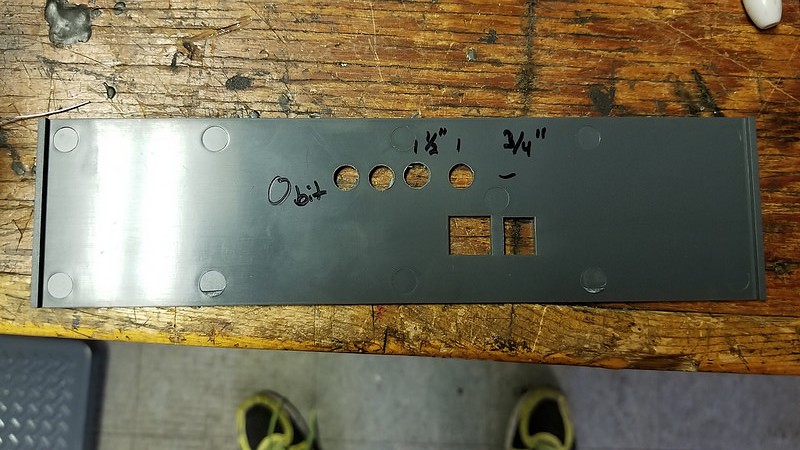
With the logic board out remove the backplate. Use a O size bit (or whatever you have that fits the sockets snugly) to drill the back plate as shown for the float switch input sockets.
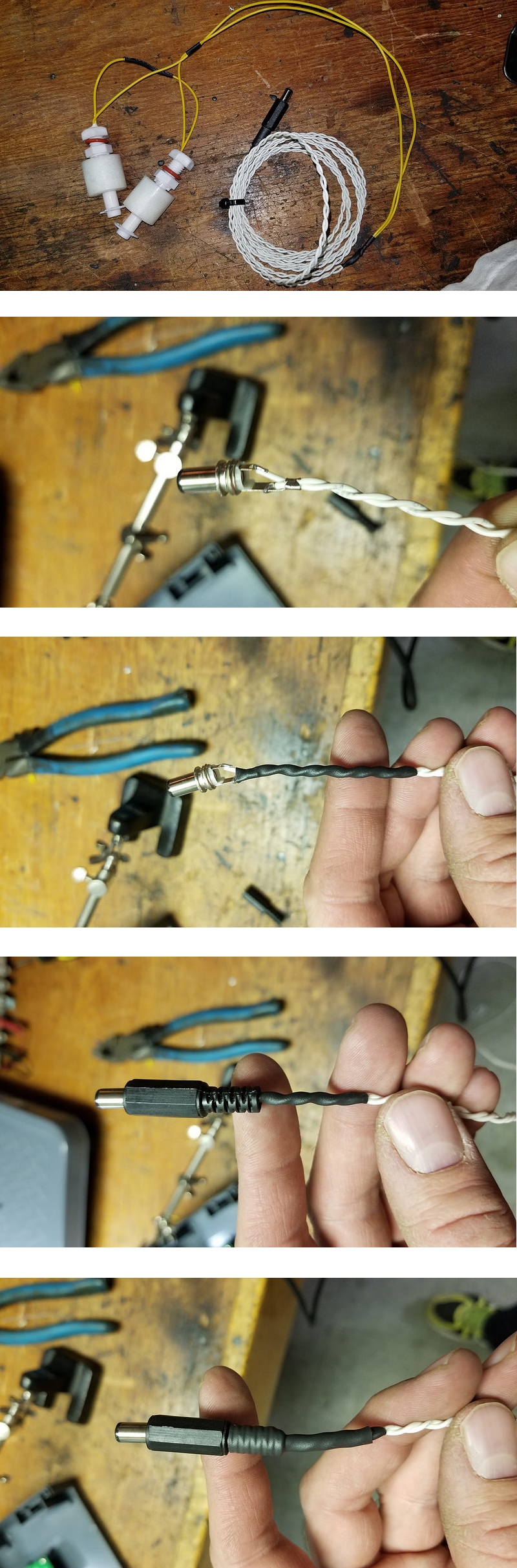
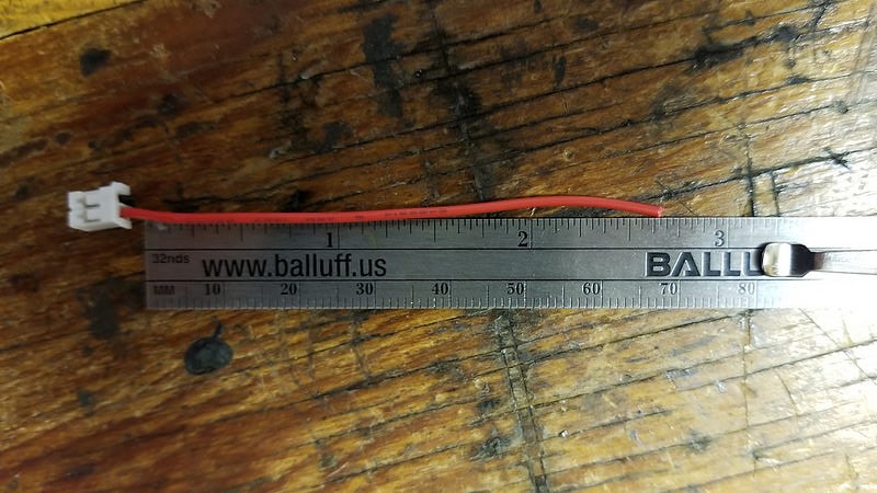
Cut the plugs off of the motors. Cut the black wire as short as you can but leave about 2.5" of the red wire intact.
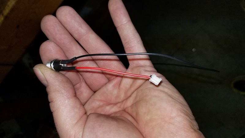
Strip back a small amount of insulation, slip some heat shrink tubing over the wire, and solder this wire to the shortest tab on the socket. Note the orientation of the socket in the image...
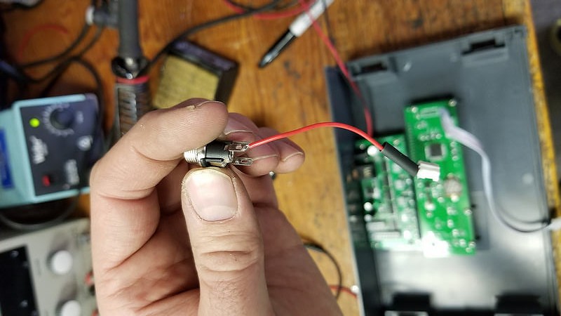
Solder an additional wire (black) to the middle (medium) pin on the connector. Apply heat shrink tubing to this pin as well.
Re-install the back plate, the logic board, and install the female connector. Plug the red wire back into the logic board as shown. Go ahead and mark the outside of the back plate with the corresponding number on the logic board so you don't get confused later on (LED1,2,3,or 4).
Repeat this step for the other 3 Female connectors as shown.
I'm sure there are other ways to do this but I feel like this is a cheap and reliable way to create a bunch of Auto Top Off systems for those folks who need several setups or for someone who needs an ATO and has a spare channel on their dosing pump, Modifying only one channel would allow you to use it as an ATO.
Hope this is helpful to someone
. Enjoy!Supplies needed...
Jebao DP-4 Dosing Pump (others hobbby pumps will probably work in a similar manner)
Float Switches
Connectors - Plugs and Sockets
Relay Board
Marine Grade Heat Shrink Tubing
Various size heat shrink tubing.
6-32 Button Head Screws 2" Long and an extra pack of nuts.
Wire ~22ga
Screwdrivers
Wire Strippers
Soldering Iron - Use a good one
In case you aren't sure, this is the one we are talking about. It's a 4 head pump. I purchased mine via international snail mail for about $55ea. Make sure it functions before taking it apart!
First step is to open up the case. The silver tabs on the front slide up towards you if you are looking at the screen, this gives you access to the clips. Prod in here with a slotted screwdriver. Take care not to drop the pump assembly when taking the case apart. It is best to do this with the screen facing the ground and removing the back of the case from the front.
Once open with the screen facing a bench, this is what we have. Go ahead and unplug all of the cables and remove the pump assembly, set it aside. Remove the 4 Phillips screws that hold the logic board, we will mod it in the next step (pictured at the top)
We need to tap into the 12v power supply to drive our relay board. On the back of the logic board solder two wires to the shown solder joints. Take care not to overheat the board. Use 12" wires here, they will be cut to length at a later time. Note polarity and be sure you can identify which is positive and negative once the board is in place.
With the logic board out remove the backplate. Use a O size bit (or whatever you have that fits the sockets snugly) to drill the back plate as shown for the float switch input sockets.
Cut the plugs off of the motors. Cut the black wire as short as you can but leave about 2.5" of the red wire intact.
Strip back a small amount of insulation, slip some heat shrink tubing over the wire, and solder this wire to the shortest tab on the socket. Note the orientation of the socket in the image...
Solder an additional wire (black) to the middle (medium) pin on the connector. Apply heat shrink tubing to this pin as well.
Re-install the back plate, the logic board, and install the female connector. Plug the red wire back into the logic board as shown. Go ahead and mark the outside of the back plate with the corresponding number on the logic board so you don't get confused later on (LED1,2,3,or 4).
Repeat this step for the other 3 Female connectors as shown.