TheFishGuy31
New member
I needed to replace the black boxes over my 75g & I wanted either the Kessil AP700s or the AI Hyrda 26 HDs. Being that I'm going to a 125g I wasn't willing to spend $2700 on the AP700s.
I realized that BRS had all of the information I needed to make my own fixtures based on the Hydra 26 HD.
First is the picture with the LED layout (from BRS):

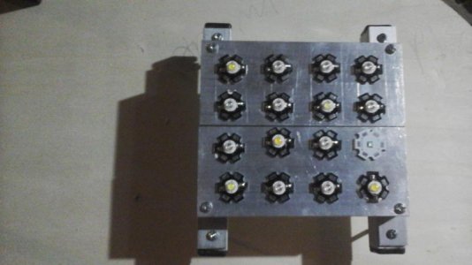
Here is the LEDs per fixture as per BRS' website:
6 - Cree XP-G2 Cool White (> 70 CRI)
6 - Cree XT-E Royal Blue
6 - Cree XP-E2 Blue
2 - OSRAM OSLON Deep Red
2 - Cree XP-E2 Green
2 - SemiLED 415nm
2 - SemiLED 400nm
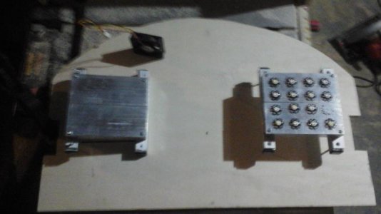
I ordered three heat sinks from RapidLED:


Pasted the LEDs onto the heatsinks using Arctic Silver & wired them so that each fixture has a channel for Blues, Royal Blues, Whites, Reds, Greens, & 400/420nm violets.

I used Meanwell LDD-700H 700mA drivers powered by a 30vDC 15A power supply.


LEDs powered up:

Full tank shot:

The color mix is one that I found on RC:
Blue/RB = 75%
White = 45%
Violet = 65%
Red = 40%
Green = 40%
I use a pot as an input to an arduino to control the total power output, & then each color value is multiplied against the total power so I can adjust the brightness of the fixtures while keeping the color ratio the same.
I still need to get project boxes to house all of the drivers & the Ardunio, as well as build the hood for the 125g so I can mount everything in it.
Feel free to ask any questions or make any comments.
I realized that BRS had all of the information I needed to make my own fixtures based on the Hydra 26 HD.
First is the picture with the LED layout (from BRS):
Here is the LEDs per fixture as per BRS' website:
6 - Cree XP-G2 Cool White (> 70 CRI)
6 - Cree XT-E Royal Blue
6 - Cree XP-E2 Blue
2 - OSRAM OSLON Deep Red
2 - Cree XP-E2 Green
2 - SemiLED 415nm
2 - SemiLED 400nm
I ordered three heat sinks from RapidLED:
Pasted the LEDs onto the heatsinks using Arctic Silver & wired them so that each fixture has a channel for Blues, Royal Blues, Whites, Reds, Greens, & 400/420nm violets.
I used Meanwell LDD-700H 700mA drivers powered by a 30vDC 15A power supply.
LEDs powered up:
Full tank shot:
The color mix is one that I found on RC:
Blue/RB = 75%
White = 45%
Violet = 65%
Red = 40%
Green = 40%
I use a pot as an input to an arduino to control the total power output, & then each color value is multiplied against the total power so I can adjust the brightness of the fixtures while keeping the color ratio the same.
I still need to get project boxes to house all of the drivers & the Ardunio, as well as build the hood for the 125g so I can mount everything in it.
Feel free to ask any questions or make any comments.
")