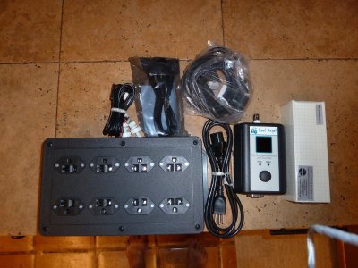
I ordered the Reef Angel reef controller yesterday. I knew they were backordered but for $200 bucks I couldn't pass it up. I recieved an email from the owner letting me know it would be shipping shortly and to feel free to email him with any questions or if I needed coding help. It is basically a blank controller platform that you code whatever you want it to do into it. It comes preloaded with some basic reef programs that work fine for most users. Included in the package is 1ph probe, 2 float switches, 3 temp probes, data cables, pwm controllers, and an 8 outlet relay box. I will post some pics when it arrives.
- Forum
- More Forums
- Reef Club Forums
- SouthWest Region-Reef Club Forums
- Arizona - Fish & Reef Aquarium Group (FRAG)
You are using an out of date browser. It may not display this or other websites correctly.
You should upgrade or use an alternative browser.
You should upgrade or use an alternative browser.
Reef Angel Controller
- Thread starter jgrog76
- Start date
usefulidiot213
Bryan H.
Whooo... New toys  Post some pics when it shows up. I want to check this doo-hicky out.
Post some pics when it shows up. I want to check this doo-hicky out.I am going to guess the relay box will not be an issue. It was designed specifically for a reeftank and to run ato and dosing pumps. Nobody on the google groups or other forums has reported anything but minor programming bugs so far. I received an email this morning that my controller was shipped! So much for the wait I guess. It is coming from CA so it should be here by this weekend.
FireC is right, the Reefkeepers use 2 different types of relays in their pc4s for this reason. My little JBJ fan would not turn off after it turned on. I switched to the other type of outlet and had no issues. Low voltage things like fans, small pumps (like the ones used for ATO), and possibly even LEDs might not work.
Just a heads up, let us know how it works out for you.
Just a heads up, let us know how it works out for you.
FiReC
Member
As far as I know, all solid state relays used in reef controllers have the same problem with low power factor... so the question still remains.. whats on the reef angel?
Neptunes response before they added mechanical relays was 'plug more stuff in' lol
Good way to cause a flood, or nuke a tank with alk when you first start messing with controllers like I almost did.
Neptunes response before they added mechanical relays was 'plug more stuff in' lol
Good way to cause a flood, or nuke a tank with alk when you first start messing with controllers like I almost did.
I dont know what type is on the reefangel. I do know that people are using it for ac dosing pumps (for example run 10 seconds every hour) and ato though without problems. It will be one of the first things I will try out when I get it because ato is one of my intended uses. Why would an aqualifter be any different than turning of a K1? They both pull about the same amount of watts. For all I know it could run a low voltage relay like on the ATO kits from autotoppoff which seem to never have trouble turning of a pump that runs at 4 watts.
Frank AZ
New member
Its not uncommon for the SSR's to have issues with low power factors.
In my case (Christmas lights controls) - I will use a high-sensitivity triac (the current switching part of an SSR) which helps significantly with the lower-current things such as LED sets. Only issue is the higher sensitivity ones that I use are also lower current (max 4a instead of 8 or 16)
My high current (40 amps/each) SSRs a set of LED's will remain fully ON due to the low factor.
I emailed the guy who designed, builds, and does the programming for the controller.
This is his response-My controller does not use Solid State Relays, which are known to cause that type of problem.
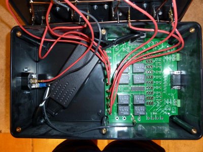
My relays are actually mechanical. All 8 of them.
The mechanical relays are the ones that you can hear a click everytime it activates and are the ones they tell you to use when you have that type of problem on other controllers.
I chose to use them vs SSR because of that reason, even though they cost more and their size is much bigger than SSR.
So i am guessing it works like an ato kit. A low voltage relay that turns the 120 plug off and on to prevent the sticking (low wattage,) and welding (high wattage) issues.
This is his response-My controller does not use Solid State Relays, which are known to cause that type of problem.
My relays are actually mechanical. All 8 of them.
The mechanical relays are the ones that you can hear a click everytime it activates and are the ones they tell you to use when you have that type of problem on other controllers.
I chose to use them vs SSR because of that reason, even though they cost more and their size is much bigger than SSR.
So i am guessing it works like an ato kit. A low voltage relay that turns the 120 plug off and on to prevent the sticking (low wattage,) and welding (high wattage) issues.
Frank AZ
New member
@Frank - Don't mean to hijack the thread. But the right value cap in parrallel with the load should offset that.
We actually use a 1w 40ohm resistor to provide a dummy load on the triac. The Cap would cause issues with the dimming functions. You really don't want to attempt to dim motors as that can cause issues with the SSR and the motor itself.
Mechanical relays will work well for this type of aplication - they aren't under any excess stress (such as switching them on/off 20 times a second) that can cause premature wear.
Of course - I'm an electronics "tinkerer" not an expert.
I did take a few peeks at the project and it does look promising - its nice that he put out the eagle files for the boards so they could be easily manufacturered by pretty much anyone.
FiReC
Member
I emailed the guy who designed, builds, and does the programming for the controller.
This is his response-My controller does not use Solid State Relays, which are known to cause that type of problem.
My relays are actually mechanical. All 8 of them.
The mechanical relays are the ones that you can hear a click everytime it activates and are the ones they tell you to use when you have that type of problem on other controllers.
I chose to use them vs SSR because of that reason, even though they cost more and their size is much bigger than SSR.
So i am guessing it works like an ato kit. A low voltage relay that turns the 120 plug off and on to prevent the sticking (low wattage,) and welding (high wattage) issues.
8 mechanical relays ... its a beautiful thing!
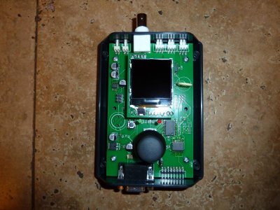
I opened the box this morning when I got home from work. Here are the pics. I haven't loaded the software or turned it on yet but I will post again with how that goes. I am a complete newbie when it comes to programming so it will be a good test of "anybody can do it." The insides look well assembled, and it is nice to see removeable connections so it can be fixed or modified later on. The float switches come with no connector on them, but there is in the box. This is good because the floats look pretty cheap and I can use the ones already installed in the sump by wiring into them with the supplied connectors. The writing on the relays says each is good for 10 amps.
Attachments
So far I have managed to lock the controller up, black screen it, learned to download all the appropriate premade codes/programming, and then reinstalled the original demo software, changed that to a version that will work a little better for me, and am starting to customize the menus. I have 0 coding experience so this is a whole new world for me.
Not trying to hijack here...but I bought one of these last week (LOVE it so far) but am wondering how to set up the ATO? What is the best way to mount the sensors for the ATO, and how to connect the sensors to the plug (they came in separate pieces)?
Any help would be much appreciated. Thanks!
Any help would be much appreciated. Thanks!
Similar threads
- Replies
- 0
- Views
- 676
- Replies
- 1
- Views
- 436
- Replies
- 10
- Views
- 1K
- Replies
- 11
- Views
- 549