djmx2002
Premium Member
Hey all,
Just thought I would share what I've been working on in the past couple of weeks.
I currently own an apex unit, and got 4 tanks with custom built radion g3 packs on them. At the moment, I can't easily control the color of the lights, since each tank has 6 channels of color.
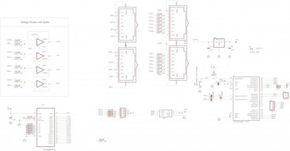
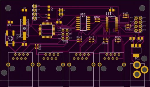
So i came up with the following solution:
each VDM port, has two channels, one would be used for defining the color, and one would be used to define the channel intensity.
I am planning on storing preset color combination based on 0-10v value. for example
91%-100% would be 15k
81%-90% would be 20k and so on.
Planning to open source the project once completed.
I am not an electrical engineer, and this is kind the first attempt at something like that, if anyone who has experience wants to help out, you're welcome")
Just thought I would share what I've been working on in the past couple of weeks.
I currently own an apex unit, and got 4 tanks with custom built radion g3 packs on them. At the moment, I can't easily control the color of the lights, since each tank has 6 channels of color.
So i came up with the following solution:
each VDM port, has two channels, one would be used for defining the color, and one would be used to define the channel intensity.
I am planning on storing preset color combination based on 0-10v value. for example
91%-100% would be 15k
81%-90% would be 20k and so on.
Planning to open source the project once completed.
I am not an electrical engineer, and this is kind the first attempt at something like that, if anyone who has experience wants to help out, you're welcome