daytonajim00
New member
I hate wires and timers and clutter! I love the idea of open source. I recently discovered the Raspberry Pi and set out to build a controller for my lighting and equiptment.
The task seems daunting at first glance. But once you know the "skinny" on what's needed and understand certain aspects of a proper install, the build is pretty simple.
There are (3) main components of this Raspberry Pi relay controller:
1) Raspberry Pi
2) Relay module
3) And receptacle to make a receptacle bank

Excuse me if my terminology is off- I'm no expert...
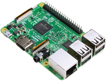
For those who don't know- The Raspberry Pi is a small computer that many people use for projects like this. It has WiFi and ports to plug in a monitor, USB keyboard/mouse, etc. You use the micro SD slot to run a card loaded with the operating system and it functions much like any other common system (windows, mac, etc.) The common operating systems ran on these Pi's are open source meaning they were collectively built through a worldwide network of programmers, and are free. The SD card functions as the hard drive so after the OS is loaded, whatever space is left over on the card is used for system storage. I have a 32GB card with something like 28G's of free space on my reef controller-this project won't need massive storage so I could of used a smaller card.
The Raspberry Pi has an GPIO (In/Out) pins that need to be utilized for a project like this- controlling relays that close 120v contact points to turn things on and off. A $10 relay module is used for this purpose. In this instance, the aquariums lights and equiptment are turned on and off based off a program that is installed. There are several reef controller programs that you can download on the Raspberry Pi but I settled on "ReefPi". I found it the most efficient, stable, and streamlined for what I need which is simply various aquarium power sources controlled off timing schedules.
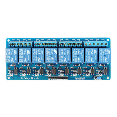
I decided to go with a $10 8-channel relay module made by Sainsmart. This is a board with 8 individual relays and 8 signal inputs. We wire 8 signal wires from the Raspberry's GPIO pins to each channel. There is a constant 120v hot "waiting" on one side of the relay, and on the other side we leave the relay to the receptacle. In short, receptacle is turned on and off via the relay controlled by a seperate signal wire.

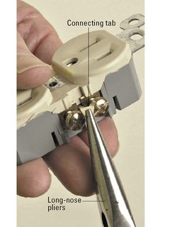
I had to build a receptacle bank because I needed 8 individual channels to control- though I'm only using 6 currently (White, Actinic, Return, Auxillary Pumps, Skimmer, refugium light). The picture I showed of the white receptacle is more accurately a "duplex receptacle" because it has two receptacles in one device. We commonly call it a receptacle but that is not entirely correctly. There is a metal tab on the device in which you can remove to isolate each receptacle. That way I need only (4) duplex receptacles which is actually (8) individual receptacles electrically separated. Might sound confusing but it's simple.
That is the intro to how to build the hardware porting of a Raspberry Pi controller. I will add more soon for anyone who is interested and hopefully if may be more clear...
The task seems daunting at first glance. But once you know the "skinny" on what's needed and understand certain aspects of a proper install, the build is pretty simple.
There are (3) main components of this Raspberry Pi relay controller:
1) Raspberry Pi
2) Relay module
3) And receptacle to make a receptacle bank
Excuse me if my terminology is off- I'm no expert...
For those who don't know- The Raspberry Pi is a small computer that many people use for projects like this. It has WiFi and ports to plug in a monitor, USB keyboard/mouse, etc. You use the micro SD slot to run a card loaded with the operating system and it functions much like any other common system (windows, mac, etc.) The common operating systems ran on these Pi's are open source meaning they were collectively built through a worldwide network of programmers, and are free. The SD card functions as the hard drive so after the OS is loaded, whatever space is left over on the card is used for system storage. I have a 32GB card with something like 28G's of free space on my reef controller-this project won't need massive storage so I could of used a smaller card.
The Raspberry Pi has an GPIO (In/Out) pins that need to be utilized for a project like this- controlling relays that close 120v contact points to turn things on and off. A $10 relay module is used for this purpose. In this instance, the aquariums lights and equiptment are turned on and off based off a program that is installed. There are several reef controller programs that you can download on the Raspberry Pi but I settled on "ReefPi". I found it the most efficient, stable, and streamlined for what I need which is simply various aquarium power sources controlled off timing schedules.
I decided to go with a $10 8-channel relay module made by Sainsmart. This is a board with 8 individual relays and 8 signal inputs. We wire 8 signal wires from the Raspberry's GPIO pins to each channel. There is a constant 120v hot "waiting" on one side of the relay, and on the other side we leave the relay to the receptacle. In short, receptacle is turned on and off via the relay controlled by a seperate signal wire.
I had to build a receptacle bank because I needed 8 individual channels to control- though I'm only using 6 currently (White, Actinic, Return, Auxillary Pumps, Skimmer, refugium light). The picture I showed of the white receptacle is more accurately a "duplex receptacle" because it has two receptacles in one device. We commonly call it a receptacle but that is not entirely correctly. There is a metal tab on the device in which you can remove to isolate each receptacle. That way I need only (4) duplex receptacles which is actually (8) individual receptacles electrically separated. Might sound confusing but it's simple.
That is the intro to how to build the hardware porting of a Raspberry Pi controller. I will add more soon for anyone who is interested and hopefully if may be more clear...