paulywog0667
Member
Hello all!
I recently set up a new 55 gallon tank. With a DIY cedar stand, sump, base rock live sand, LED lighting(blue and white no dimmer). It is currently cycling. I just set up auto top off for it!") Have some diatoms. So letting them stabilize things and waiting for them to go away. Figure since it was base rock, I am nearing the end of the cycle. (Tests will tell) Recently, I have decided to add in an open source DIY mini controller. A little history of myself; I used to run a traffic department for a municipality. Where the controllers for the intersections, worked very similar to an aquarium controller; timers, sensors, etc...
Have some diatoms. So letting them stabilize things and waiting for them to go away. Figure since it was base rock, I am nearing the end of the cycle. (Tests will tell) Recently, I have decided to add in an open source DIY mini controller. A little history of myself; I used to run a traffic department for a municipality. Where the controllers for the intersections, worked very similar to an aquarium controller; timers, sensors, etc...
It was always nice because many manufacturers will provide free software. To assign pin operations, phases, etc. My dilemma is, I switched my operating system to linux! lol Most places only have windows based software. My experience was in the wireing and software, not the actual scripting. I now see how privileged I was, having drag and drop menus and enter a pin and a designation or what I wanted it to do. With the Linux, I do not think I will get that luxery with my aquarium. So I have been studying the Arduino system. I came up with the following basic script for lights and two steady on relays. I read Arduinos only can handle so many counts. If I set the millis down to say around 10 seconds. The script runs fine. For some reason as written, relay 2 will not turn back off. I am assuming it might be too long of a duration delay? Does anyone know a better way for this basic time schedule of relay 3&4 always on. Then relay1 on, an hour later, relay2 on, 8 hours later, relay 2 off, then an hour later, relay one off. Then I have it delayed for 14 hours to then repeat the loop indefinitely. The delays are in milli seconds. That is why the large numbers. I have an RTC and also read about blinking led for a schedual. Figured while I am researching it, I would ask here for some advice. Here is my script!!!!! Please check.
The original is an Arduino example, Then I completely changed it. Just starting on this type of stuff.... SOOOO I am a noobe! lol More than adequate experience for the wiring though.
Thank you in advance..
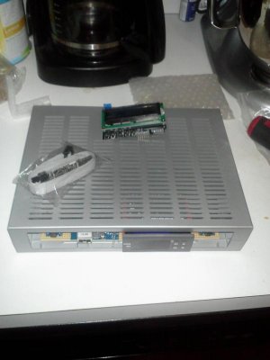
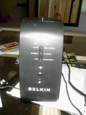
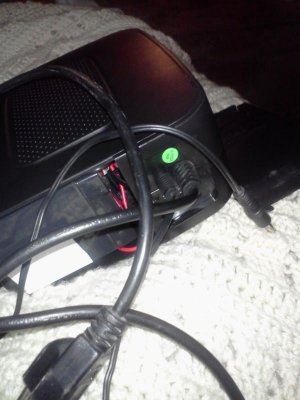
p.s. I included a couple pics of the hardware I have. Kind of hard to toss the wires in, before I am aware of possible conflicts and rules of scripts. ( I miss my old traffic software!lol)
/* Basic lighting and two extra outlets: Arduino Control
Handles "Relay is active-low" to assure
no relay activation from reset until
application is ready.
/*-----( Import needed libraries )-----*/
/*-----( Declare Constants )-----*/
#define RELAY_ON 0
#define RELAY_OFF 1
/*-----( Declare objects )-----*/
/*-----( Declare Variables )-----*/
#define Relay_1 2 // Arduino Digital I/O pin number
#define Relay_2 3 // d3 on Arduino to relay#2 etc, etc,...
#define Relay_3 4
#define Relay_4 5
void setup() /****** SETUP: RUNS ONCE ******/
{
//-------( Initialize Pins so relays are inactive at reset)----
digitalWrite(Relay_1, RELAY_OFF);
digitalWrite(Relay_2, RELAY_OFF);
digitalWrite(Relay_3, RELAY_OFF);
digitalWrite(Relay_4, RELAY_OFF);
//---( THEN set pins as outputs )----
pinMode(Relay_1, OUTPUT);
pinMode(Relay_2, OUTPUT);
pinMode(Relay_3, OUTPUT);
pinMode(Relay_4, OUTPUT);
delay(4000); //Check that all relays are inactive at Reset
digitalWrite(Relay_3, RELAY_ON);// turns relay3 on
digitalWrite(Relay_4, RELAY_ON // turns relay4 on
delay(3000); //so a 3 second delay before lights on
}//--(end setup )---
void loop() /****** LOOP: RUNS CONSTANTLY ******/
{
//---( Turn blue and white led relays ON in sequence)---
digitalWrite(Relay_1, RELAY_ON);// set the Relay ON
delay(3600000);
digitalWrite(Relay_2, RELAY_ON);// set the Relay ON
delay(28800000);
//---( Turn white then blue leds OFF in sequence)---
digitalWrite(Relay_2, RELAY_OFF);// set the Relay OFF
delay(3600000);
digitalWrite(Relay_1, RELAY_OFF);// set the Relay OFF
delay(57600000);
}//--(end main loop )---
I recently set up a new 55 gallon tank. With a DIY cedar stand, sump, base rock live sand, LED lighting(blue and white no dimmer). It is currently cycling. I just set up auto top off for it!
Have some diatoms. So letting them stabilize things and waiting for them to go away. Figure since it was base rock, I am nearing the end of the cycle. (Tests will tell) Recently, I have decided to add in an open source DIY mini controller. A little history of myself; I used to run a traffic department for a municipality. Where the controllers for the intersections, worked very similar to an aquarium controller; timers, sensors, etc...It was always nice because many manufacturers will provide free software. To assign pin operations, phases, etc. My dilemma is, I switched my operating system to linux! lol Most places only have windows based software. My experience was in the wireing and software, not the actual scripting. I now see how privileged I was, having drag and drop menus and enter a pin and a designation or what I wanted it to do. With the Linux, I do not think I will get that luxery with my aquarium.
So I have been studying the Arduino system. I came up with the following basic script for lights and two steady on relays. I read Arduinos only can handle so many counts. If I set the millis down to say around 10 seconds. The script runs fine. For some reason as written, relay 2 will not turn back off. I am assuming it might be too long of a duration delay? Does anyone know a better way for this basic time schedule of relay 3&4 always on. Then relay1 on, an hour later, relay2 on, 8 hours later, relay 2 off, then an hour later, relay one off. Then I have it delayed for 14 hours to then repeat the loop indefinitely. The delays are in milli seconds. That is why the large numbers. I have an RTC and also read about blinking led for a schedual. Figured while I am researching it, I would ask here for some advice. Here is my script!!!!! Please check.The original is an Arduino example, Then I completely changed it. Just starting on this type of stuff.... SOOOO I am a noobe! lol More than adequate experience for the wiring though.
Thank you in advance..
p.s. I included a couple pics of the hardware I have. Kind of hard to toss the wires in, before I am aware of possible conflicts and rules of scripts. ( I miss my old traffic software!lol)
/* Basic lighting and two extra outlets: Arduino Control
Handles "Relay is active-low" to assure
no relay activation from reset until
application is ready.
/*-----( Import needed libraries )-----*/
/*-----( Declare Constants )-----*/
#define RELAY_ON 0
#define RELAY_OFF 1
/*-----( Declare objects )-----*/
/*-----( Declare Variables )-----*/
#define Relay_1 2 // Arduino Digital I/O pin number
#define Relay_2 3 // d3 on Arduino to relay#2 etc, etc,...
#define Relay_3 4
#define Relay_4 5
void setup() /****** SETUP: RUNS ONCE ******/
{
//-------( Initialize Pins so relays are inactive at reset)----
digitalWrite(Relay_1, RELAY_OFF);
digitalWrite(Relay_2, RELAY_OFF);
digitalWrite(Relay_3, RELAY_OFF);
digitalWrite(Relay_4, RELAY_OFF);
//---( THEN set pins as outputs )----
pinMode(Relay_1, OUTPUT);
pinMode(Relay_2, OUTPUT);
pinMode(Relay_3, OUTPUT);
pinMode(Relay_4, OUTPUT);
delay(4000); //Check that all relays are inactive at Reset
digitalWrite(Relay_3, RELAY_ON);// turns relay3 on
digitalWrite(Relay_4, RELAY_ON // turns relay4 on
delay(3000); //so a 3 second delay before lights on
}//--(end setup )---
void loop() /****** LOOP: RUNS CONSTANTLY ******/
{
//---( Turn blue and white led relays ON in sequence)---
digitalWrite(Relay_1, RELAY_ON);// set the Relay ON
delay(3600000);
digitalWrite(Relay_2, RELAY_ON);// set the Relay ON
delay(28800000);
//---( Turn white then blue leds OFF in sequence)---
digitalWrite(Relay_2, RELAY_OFF);// set the Relay OFF
delay(3600000);
digitalWrite(Relay_1, RELAY_OFF);// set the Relay OFF
delay(57600000);
}//--(end main loop )---