Gorgok
New member
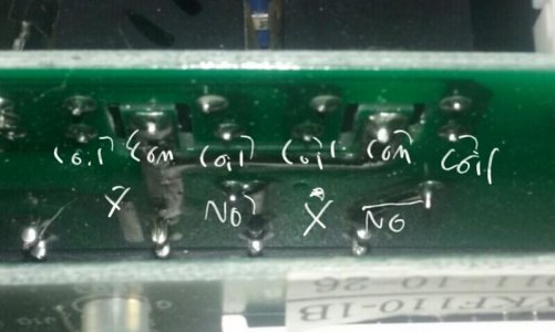
It means the coils are working and the brains sound to be as well. But the coils just move a arm which is the actual contact. If the relays are not welded then the output contacts should be either 0V or 110V AC... (If it has welded then it will be 110V AC all the time)
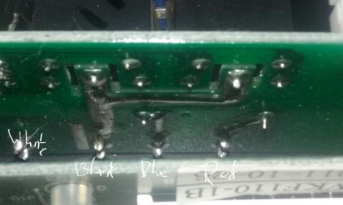
The output pins should be the pins in the middleish of the board with the fat solder lines coming from them. They probably just go to the blue/red blade connections though, so testing there would be easier.
Another easy test would be to swap the red and blue wires. If the cooler doesn't start running right off when plugged back in, the cooler circuit was stuck on. The heater plug should now be hot at all times, and the cooler will only turn on if the temperature is too low, but at least it proves the culprit is just the relay.