Closed loop pump inlet pipe: size to pump *at* pump or far end of "10D" straightway?

Which is better to avoid cavitation?

  • Option A: 1" pipe for straightway

    Votes: 0 0.0%
  • Option B: 1.5" pipe for straightway

    Votes: 0 0.0%

  • Total voters
    0

FlyingShawn

New member
Hello all!

I'm experiencing cavitation on the Sicce SDC 9.0 pump running my closed loop even if I dial it down to minimum "throttle" on the controller. No bubbles in my flow meter downstream, just a popping/whirring/whooshing sound at the pump inlet. It's honestly not a surprise given my intake setup and the extremely-cramped space in the stand under my 52gal tank, so I'm working on a solution and need advice about a specific element of the design...

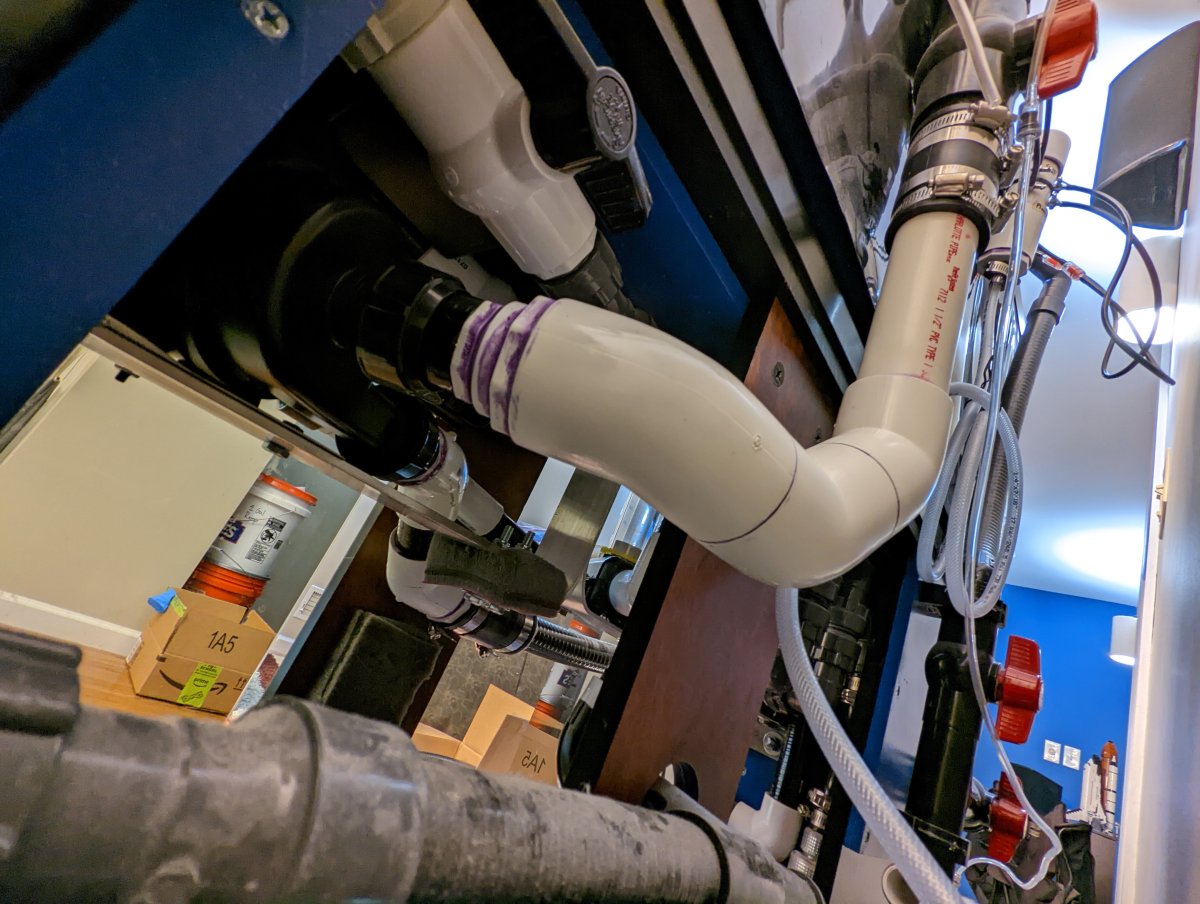
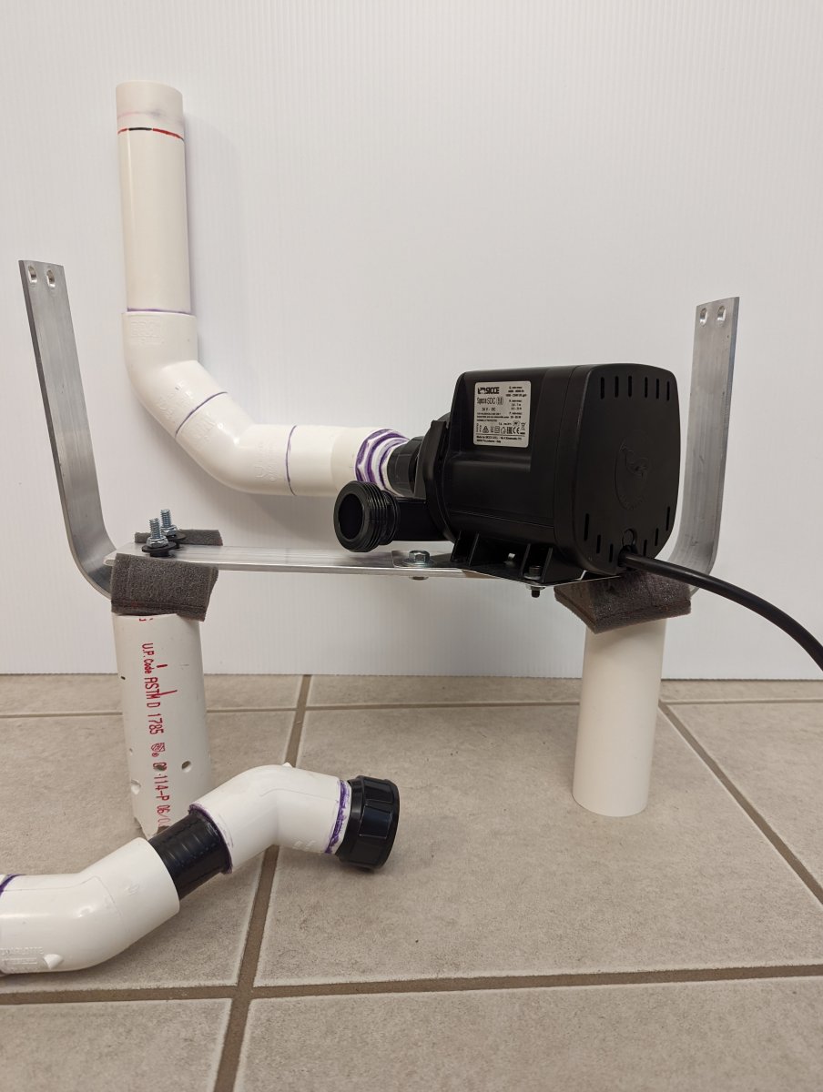
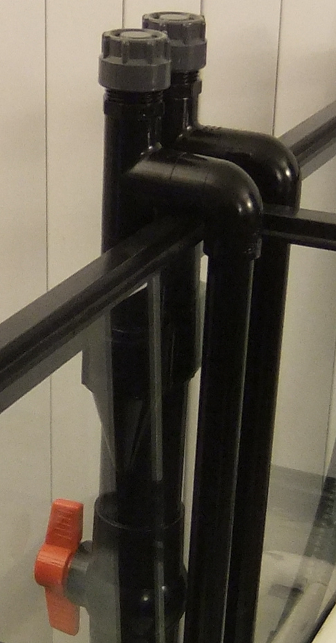
First, an overview of the current inlet pipe causing the problems... Water comes over the side of the tank through two 3/4" siphon lines and through a large Y to combine into a 1.5" pipe before passing through three 45 elbows and a series of reducers to match the Sicce's 1" inlet. The dual 3/4" pipes were a consequence of the tank layout (preferring a central intake despite the presence of a center brace, plus also wanting smaller pipes in-tank) and the idea to combine into a 1.5" master drain was an attempt to offset the negative flow effects of the elbows and minimize resistance.
1660167542522.png
1660166122514.png


2022-07-23 18.52.53.jpg
2022-07-23 17.34.01.jpg


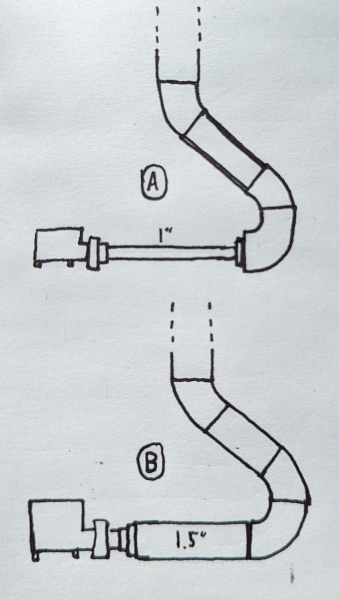
This obviously hasn't worked, so now I'm considering a new strategy that's compatible with the "10D" rule of running a straight section of pipe 10x the pump's input diameter before any elbows. In my case that'd be 10", extending all the way to the house wall behind the tank, and would require more elbows (which is, of course, undesirable and what I was originally trying to avoid) so the pipe could double-back on itself. Here's my question: where do I put the reducer bushings to bring the pipe down to 1"? (please forgive the quality of the sketch)
2022-08-10 17.25.21-1.jpg


Option "A" would potentially have the advantage of smoother flow to the pump because the only restriction between the 10" run of 1" pipe and the pump would be a 1" MPT adapter, but would come with more overall flow resistance.
- on the other hand -
Option "B" would have less flow resistance by keeping the much larger 1.5" diameter for the 10" straight section, but would require multiple step-down reducers at the pump's mouth (like in the pictures above) or one big step in the form of a 1.5" slip to 1" MPT fitting (an uncommon part I'd have to order from FlexPVC).

What do you think? If it helps, my goal isn't to run this pump full-out: it's a replacement for a much noisier Iwaki pushing water through two Nu-Clear canisters and other in-line accessories (UV, heater, purigen, etc, all on valved bypass lines) and I'll likely want to run it at about 50% throttle. Thanks!
 
Welcome to RC! I have no idea how to answer your question but hopefully others can chime in
 
Welcome ot RC! The combined cross section of two 3/4" pipes should be close to the cross section of one 1" pipe so I'd think flow is not restricted that much. To answer your question though I would go with fewer elbows and maybe consider flexable tubing. Have yoe opened up th evolute to see if tehre's debris hitting the impellor? Have you tried turning the pump on and off several time to make sure all the air has been pushed out og the volute?
 
one big step in the form of a 1.5" slip to 1" MPT fitting (an uncommon part I'd have to order from FlexPVC)
^best option if it's vacuum cavitation as you assume. It could also be aeration because of turbulence created by your 'y' assembly. Are you achieving full syphon? (If you hear noise in the down pipe you do not have a full syphon). It also can be discharge cavitation if there is output blockage or a control valve too closed.
 
Welcome to RC! I have no idea how to answer your question but hopefully others can chime in
Welcome ot RC!
Thanks for the welcomes! I'll confess I'm a freshwater hobbyist, but while researching this issue I found some truly excellent discussions on the subject in the RC archives and I knew I was far more likely to find the answers I needed here than my usual resources!
The combined cross section of two 3/4" pipes should be close to the cross section of one 1" pipe so I'd think flow is not restricted that much.
I agree. Based on my calculations using the FlexPVC flow charts the cross section of the two 3/4" pipes is anywhere from 112-145% the cross section of a 1" pipe (they list the ID of the 3/4 as ranging between 0.75-0.85", hence the large % range), which is why I felt I could get away with the dual-pipe arrangement.

To answer your question though I would go with fewer elbows and maybe consider flexable tubing. Have yoe opened up th evolute to see if tehre's debris hitting the impellor? Have you tried turning the pump on and off several time to make sure all the air has been pushed out og the volute?

I'd certainly prefer to use less elbows(!), but the available space is so limited that I'd only be able to use flexible PVC if I stepped down to a smaller diameter pipe immediately after the Y. I don't have the engineering/fluid dynamics knowledge to do the calculations and be sure of this, but my hunch is the 1.5" elbow arrangement in my diagram sketch would be less restrictive than doing that whole bend in 1" flexible pipe.

The water is pre-filtered at the intake, so I'm confident there's no sizable debris getting to the pump. I'm also still experiencing the cavitation noises at the pump after a number of start-stop cycles and enough runtime to finish the process of purging air from the siphon line (which is pretty noticeable after the initial priming because of all the bubbles in the flow meter), so I'm confident it's a cavitation caused by my poor original plumbing design.
 
^best option if it's vacuum cavitation as you assume. It could also be aeration because of turbulence created by your 'y' assembly. Are you achieving full syphon? (If you hear noise in the down pipe you do not have a full syphon). It also can be discharge cavitation if there is output blockage or a control valve too closed.

Thanks for weighing in! No noises in the down pipe once it's been running for a few minutes and I'm confident of full siphon (the priming caps seal with o-rings and, although it's not visible in the pictures because it was a later addition, but I have a couple of air lines drilled/siliconed/valved at the top of the priming towers that allow me to purge nearly all of the air from the assembly before the pump is first started).

I also don't believe it's discharge cavitation because the calculated head of the system should be well within the capabilities of the pump, the flow rate (even with the cavitation) seems sensible compared to the head and throttle setting, and the system is in its least-restricted configuration (clean filter cartridges, control valves on the main line full-open, and control valves on the bypass manifolds for heater/purigen/etc all full-closed so the flow is entirely through the main line).
 
1- Is this a DC pump?
If so they do NOT like head pressure & you are pushing through 2 cannister filters & more.

It is. My previous Iwaki was far too loud even with vibration dampening and sound absorbing foam in the stand, so I decided to go a different direction. Knowing that DC pumps don't generally like head pressure, I opted for a model with much more head capability than I'd need (the SDC 9.0 maxes out at 23ft of head @ zero flow) with the goal of throttling it down to match my needs and staying well within the performance envelope of the pump.

It's been a while since I ran the calculations, so I don't remember the exact numbers, but even with the canisters/plumbing/etc and erring on the side of overestimating head I think I came up with around 15-16ft of head pressure in the system. The pump's flow chart says it ought to be capable of around 1000-1100gph at 16ft head @ full throttle, so my goal of dialing it down to around 500gph on my 52gal tank should leave plenty of available headroom (pun fully intended!) to keep from straining the pump.
If everything has a bypass circuit as you alluded then testing if backpressure is the issue is easily done.
 
Well a submarine can cause cavitation & you know there are no suction leaks @ depths like they run at.
Switch back to the Iwaki for confirmation.
 
I did'ne see anywhere that you've checked but what happens if you remove the prefilter?
 
If everything has a bypass circuit as you alluded then testing if backpressure is the issue is easily done.
The bypasses rejoin the main line downstream rather than independently returning to the tank, so I can't reduce backpressure that way, but I do have one or two tricks up my sleeve that I can test: the system was designed with a valved drain port where I can hook up a hose for easy water changes, so I'll simply loop the hose back into the tank as an additional filter outlet. Should be able to try it early next week: I've been away on a work trip and won't get home for another few days.
Well a submarine can cause cavitation & you know there are no suction leaks @ depths like they run at.
Switch back to the Iwaki for confirmation.
Everything between the rubber coupler (just below the Y) and the pump had to be replaced during the upgrade to accommodate the Sicce's different location in the stand and intake diameter, so switching back wouldn't answer if it was a pump problem or an intake line configuration problem even if it was feasible (I had to rework a lot of equipment to accommodate the change because the Sicce didn't fit where I had the Iwaki located).

I'm honestly pretty confident my cavitation is due to those elbows being too close to the pump intake, which is why I started the thread. I've ordered some parts from FlexPVC that should arrive next week that'd allow me to build either of my original sketched options and I'm currently leaning toward trying Option B first (1.5" all the way with an MPT adapter that goes down to 1" in a single step).

I did'ne see anywhere that you've checked but what happens if you remove the prefilter?

I haven't, but I'm pretty sure it's not the source of the restriction. The prefilter is a modified UGF made of dual drilled PVC loops with many large (I think I went with 1/4" holes) drilled in each loop. There's a wall of acrylic around the UGF to keep my main substrate from getting pulled in and the loops themselves are covered in Matrix rocks and capped with a layer of Matala (an extremely high-flow material used for filtering ponds). I recently redid the tank and the pump upgrade was part of the process, so the UGF is still in a very clean state from the upgrade (the tank has been using an HOB in the meantime, so there should be almost no gunk settled in/around the UGF since it was last removed/cleaned).
DSCF6628~01.jpg
 
I haven't, but I'm pretty sure it's not the source of the restriction. The prefilter is a modified UGF made of dual drilled PVC loops with many large (I think I went with 1/4" holes) drilled in each loop. There's a wall of acrylic around the UGF to keep my main substrate from getting pulled in and the loops themselves are covered in Matrix rocks and capped with a layer of Matala (an extremely high-flow material used for filtering ponds). I recently redid the tank and the pump upgrade was part of the process, so the UGF is still in a very clean state from the upgrade (the tank has been using an HOB in the meantime, so there should be almost no gunk settled in/around the UGF since it was last removed/cleaned).
That looks pretty restrictive on it's own. Any idea how much that can flow?
 
That looks pretty restrictive on it's own. Any idea how much that can flow?
The UGFs are each drilled with sufficient 1/4" holes facing inward to exceed the area of a 3/4" pipe (plus there are a number of outward-angled 1/8" holes), so the intakes should be less restrictive than the 3/4" pipe they're connected to.
2014-02-07 17.11.31.jpg


I was able to do some more testing today with my backpressure-reduction mods and the problem is definitely still present. As I'm listening to it more closely at minimum pump throttle, the sound from the impeller seems to be a THWIP-THWIP-THWIP-THWIP-THWIP noise as though there's a sizeable air bubble at the top of the impeller and the sound is from the top blades exiting and reentering the water line. Speed up the pump and it's a more constant burring noise, which is either just because it's going too fast for the thwip-ing to be as distinct or it's pulling some of the air from the pocket down into the water as bubbles but it's not able to force them into the outflow.

I've also spent some time examining the top of my siphon pipes and I've discovered I might not have as perfect of a seal as I previously believed. Here's a shot showing the air lines I use to raise the water level after priming to jump-start the siphon before the pump is started: turns out the silicone around one or both of the air lines didn't fully "grab" onto the tubing leaving them able to slide in/out of the pipe holes. It'd be a very tiny air leak, but still enough of one to keep me from achieving a perfect siphon and enough to break the siphon whenever the pump is shut off (which I'm experiencing in my testing).
PXL_20220822_200659305.jpg


I still strongly suspect I'll need to rework the pump intake so the elbows aren't as close to the impeller, but before I put any work into that I'm going to need to resolve this air leak and test again. I haven't decided if I'm going to try to remove and re-silicone the air tubing to keep the priming system or if I'm going to yank the tubing and plug the holes altogether. I have another trip out of town Wednesday, so I probably won't be able to work on it and post an update until sometime next week.
 
It's a long-overdue update because I wanted to take enough time to be confident and I had work/family things to deal with, but I'm pleased to say that I was WRONG about the underlying cause of my pump intake noise: it was an air leak after all! Redoing the silicone around the intake air tubing with a much more generous application solved the problem and the pump has been running smoothly for the last two weeks!

Thanks so much for all the input: I wouldn't have suspected those silicone points if not for the discussion here forcing me to reexamine the whole intake chain!

2022-08-23 17.03.54.jpg
 
Last edited:
Back
Top