kentlighting
New member
Here is my build, enjoy!
Alright, So the build is done and in place above the tank. So far im really happy with how everything turned out.
Materals Used:
1x 48"x8.460" Extruded Aluminum Heat Sink
24x Cree Cool White XP-G Stars
24x Cree Royal Blue XP-G Stars
4 X Meanwell ELN 48-60D Drivers
48x Bergquist Thermal Pads
48X 40Degree diffused Lenses
24' 18gauge 6 conductor Cable
2 Computer fans
1 Computer Fan power supply
1 project box
4x 4 pin XLR Panel mount connectors
4x 4 pin Cable mount Male connectors\
2x 6 pin Molex Connectors
2x sets of 4 pin din connectors
2x sets of rca connectors
3/16th steel aircraft cable with various parts for suspension.
1 Apex VDM module
As you can see in the first few posts I started with the project box.

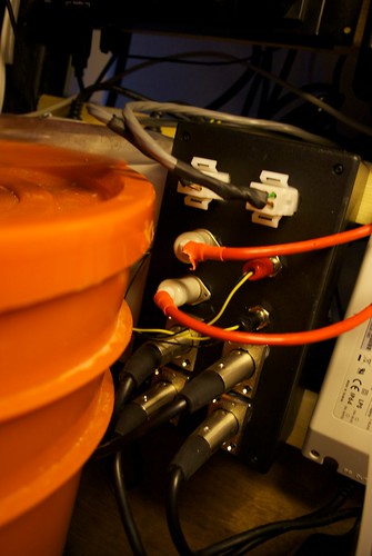
I wanted to make everything easy to switch out a driver if needed and cabling going to the fixture as minimal as possible. The Drivers Dc side combine the LEDs power and the 0-10 volt control into one 4 conductor cable. so i chose the 4 pin XLR connectors to make a single connection for each drive to do all that.

I chose XLR cause its an easy to use connector, it locks, and i know its rated for the power as professional entertainment LED lighting fixtures use the same connector.
Now any new drivers that replace the old ones if it should break needs only a XLR connector to go on and to be calibrated for the right amperage which i have mine set to 800mA.
So with that being mounted in the project box, it ment that my 0-10volt control signals needed to make it into the project box as well so they can be routed to the right driver. The VDM spits out 4 0-10 volt signals and I decided to make use of all 4 - 1 for each driver giving the greatest control of the fixture.

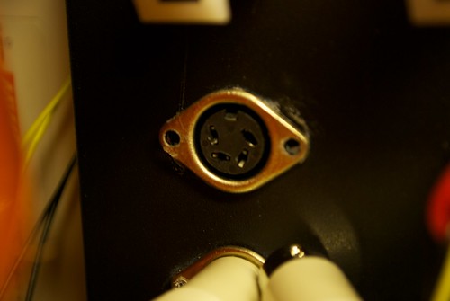
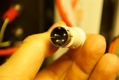
I decided to use 4 pin din connectors for bring that into the box.


On the VDM side it is a RJ 45 connector which ment I had to make 2 RJ-45 to 4 Pin Din Adaptors.

I did want to use Neutrik EtherCon connectors for this as it too is a locking connector and has the same footprint as XLR but cost a hefty amount. But it would have ment any Ethernet cable would have worked with the box. Maybe next build.
I wanted to minimize the number of cables going up to the fixture to some extent so I wanted the Fans power to go threw the box as well so i decided to go with an RCA connector to provide the DC power from the power supply for the fans into the box.

All this has to come out somewhere so that brings us to the two 6 Pin molex connectors. Each Connector provides the Power for 2 channels of LEDs (1 Blue and 1 White) and Fan Power. These Connect to two 12' sections of the 18 gauge 6 conductor cable.

The Way the wiring is done in the Box is that everything is Identical to its matching connector. so there is no way anything can get plugged into the wrong spot and damage a component nor can you plug something in the wrong connector and have the programing act weird.
Next ment actually building the fixture. I layed out a grid with sharpie of the placment of LEDs. I went with the thermal pads from Nanotuners.com as it made mounting the LEDs so easy. No Tapping and drilling to screw the LEDs in, and No expensive permenant silver thermal paste. These are basicly double sided tape cut in the shape of the stars. The easiest way i found to use these are to pull them of the sheet place them on the heat sink then pull the top part off the pad to expose the top sticky side and place the LED on that. Any other way is asking to have a pad fold over and stick to itself. To remove the LEDs from the pads you just take a small flat head screw driver and give it a tiny wack on the side of the star. With the pads this process took about 45mins of actual mounting of the LEDs.
Next Came wiring which was easy Each driver powers 12 LEDs wired in series. So power goes into the positive side of the LED out of the Negitive and into the Positive of the next one and so on. Easy.
Next Was the Lenses. I went with 40 degree Diffused Lenses to help condense the light down to the tank allowing me to suspend the fixture higher from the tank giving more working room to stick my arms into the tank and not wacking the fixture. Diffused gives me a wash with the light so there is no Spot Lighting Effect and just a nice even fade off at the Edge of the beam. The Lenses dont hold extremly well to the LEDs so i put a little Dab of super glue on the edge of each on to hold it to the star.
Alright, So the build is done and in place above the tank. So far im really happy with how everything turned out.
Materals Used:
1x 48"x8.460" Extruded Aluminum Heat Sink
24x Cree Cool White XP-G Stars
24x Cree Royal Blue XP-G Stars
4 X Meanwell ELN 48-60D Drivers
48x Bergquist Thermal Pads
48X 40Degree diffused Lenses
24' 18gauge 6 conductor Cable
2 Computer fans
1 Computer Fan power supply
1 project box
4x 4 pin XLR Panel mount connectors
4x 4 pin Cable mount Male connectors\
2x 6 pin Molex Connectors
2x sets of 4 pin din connectors
2x sets of rca connectors
3/16th steel aircraft cable with various parts for suspension.
1 Apex VDM module
As you can see in the first few posts I started with the project box.

I wanted to make everything easy to switch out a driver if needed and cabling going to the fixture as minimal as possible. The Drivers Dc side combine the LEDs power and the 0-10 volt control into one 4 conductor cable. so i chose the 4 pin XLR connectors to make a single connection for each drive to do all that.

I chose XLR cause its an easy to use connector, it locks, and i know its rated for the power as professional entertainment LED lighting fixtures use the same connector.
Now any new drivers that replace the old ones if it should break needs only a XLR connector to go on and to be calibrated for the right amperage which i have mine set to 800mA.
So with that being mounted in the project box, it ment that my 0-10volt control signals needed to make it into the project box as well so they can be routed to the right driver. The VDM spits out 4 0-10 volt signals and I decided to make use of all 4 - 1 for each driver giving the greatest control of the fixture.

I decided to use 4 pin din connectors for bring that into the box.


On the VDM side it is a RJ 45 connector which ment I had to make 2 RJ-45 to 4 Pin Din Adaptors.

I did want to use Neutrik EtherCon connectors for this as it too is a locking connector and has the same footprint as XLR but cost a hefty amount. But it would have ment any Ethernet cable would have worked with the box. Maybe next build.
I wanted to minimize the number of cables going up to the fixture to some extent so I wanted the Fans power to go threw the box as well so i decided to go with an RCA connector to provide the DC power from the power supply for the fans into the box.

All this has to come out somewhere so that brings us to the two 6 Pin molex connectors. Each Connector provides the Power for 2 channels of LEDs (1 Blue and 1 White) and Fan Power. These Connect to two 12' sections of the 18 gauge 6 conductor cable.

The Way the wiring is done in the Box is that everything is Identical to its matching connector. so there is no way anything can get plugged into the wrong spot and damage a component nor can you plug something in the wrong connector and have the programing act weird.
Next ment actually building the fixture. I layed out a grid with sharpie of the placment of LEDs. I went with the thermal pads from Nanotuners.com as it made mounting the LEDs so easy. No Tapping and drilling to screw the LEDs in, and No expensive permenant silver thermal paste. These are basicly double sided tape cut in the shape of the stars. The easiest way i found to use these are to pull them of the sheet place them on the heat sink then pull the top part off the pad to expose the top sticky side and place the LED on that. Any other way is asking to have a pad fold over and stick to itself. To remove the LEDs from the pads you just take a small flat head screw driver and give it a tiny wack on the side of the star. With the pads this process took about 45mins of actual mounting of the LEDs.
Next Came wiring which was easy Each driver powers 12 LEDs wired in series. So power goes into the positive side of the LED out of the Negitive and into the Positive of the next one and so on. Easy.
Next Was the Lenses. I went with 40 degree Diffused Lenses to help condense the light down to the tank allowing me to suspend the fixture higher from the tank giving more working room to stick my arms into the tank and not wacking the fixture. Diffused gives me a wash with the light so there is no Spot Lighting Effect and just a nice even fade off at the Edge of the beam. The Lenses dont hold extremly well to the LEDs so i put a little Dab of super glue on the edge of each on to hold it to the star.


