DIY Controller - lots of features - reasonable to build

Quite a school project! Best of luck.
If you have some big problems, feel free to post.
Although since it is a school project, I guess you can't really ask
for code too much.

LOL, it's a community college. Anything goes! :celeb1:
 
Quick update:
I finally received my relays last week. Took forever. Shipped from Hong Kong.
I am not sure futurlec is the best vendor.
So I am working on connecting those up.

Also, a fair bit of the network stuff is done.
Time update from internet NTP is reliable, and updates RTC clock module.
Data loging push out to internet is looking good.

You can see some of it here.
(Measures tank temp, one unconected, air temp, and water top off)
https://pachube.com/feeds/38937

Cool man! I was leaning in the direction of pachube myself. What a great service!
 
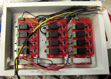
Main bank of 8 relays are done!
Picture below. Also connected up, with software, and tested.
Relay status is now on pachube web page as well.

I had 3 sets of 4, so could have done 12 relays, but decided to double-up
4 of them, for extra reliability.
So 4 normal, 4 doubled = 8 relays.

Relays can get stuck "on". And Calc/Alk/ATO stuck on is a disaster.
Doubling that up reduces the risk.
It does increase the risk of stuck off. But that is more rare, and not a
horrible problem if it happens.
 

Attachments

  • relay8.jpg
    relay8.jpg
    82.1 KB · Views: 1
quick question about the relay boards from futurlec. where did you get the ribbon cables to go with them? and where is it connected to your controller?
thanks!
 
quick question about the relay boards from futurlec. where did you get the ribbon cables to go with them? and where is it connected to your controller?
thanks!

Ribbon cables came with the relay boards.
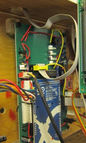
However, they are not very long, so I made one myself.
I buy most of my misc parts from Jameco

I soldered a male connector the the board, wired that up, and plugged
in the ribbon cable.
You can see it in the enclosed picture.
 

Attachments

  • rbbn1.jpg
    rbbn1.jpg
    64 KB · Views: 1
Post holiday update:

Getting close to done.

I am debugging the PWM connections.
(I made a mistake and connected a couple to standard I/O)
But seems to be working.

Ethernet, relays, temperature, Clock, and ATO sensors are all working.

I need to wire the PWM controls to the main lights.

I need to make a fancy holder for the display, and mount to tank.

Plus, I am a bit worried about one failure mode:
It turns out, if I lose power to the micro-controller, but not
the relay board, all the relays turn ON.
They are on same power supply, but not the same connector.
 

Attachments

  • system.jpg
    system.jpg
    73.1 KB · Views: 1
So are your relays wired normally open or normally closed? seems swapping that and changing the code to go from low to high or vice versa would eliminate that issue fairly easily
 
Post holiday update:

Getting close to done.

I am debugging the PWM connections.
(I made a mistake and connected a couple to standard I/O)
But seems to be working.

Ethernet, relays, temperature, Clock, and ATO sensors are all working.

I need to wire the PWM controls to the main lights.

I need to make a fancy holder for the display, and mount to tank.

Plus, I am a bit worried about one failure mode:
It turns out, if I lose power to the micro-controller, but not
the relay board, all the relays turn ON.
They are on same power supply, but not the same connector.

I have had a similar experience, when my controller resets all of the relays blink for about 1/2 second. I am not too worried about this, though I am thinking a small backup battery would prevent some of this.
 
Regarding relay issue:
The problem is:
At boot, your I/O are tristate, so float.
However, if you disconnect power to board, the I/O go low.
(Probably due to protection diodes pulling to power rail, which is zero)

The relays are active low. So when it power off, they go on.
I could switch them to normally open mode.
But that scares me a bit as well, since during boot, the relays will be on.
And if something goes wrong, and board resets, they go on and maybe stay on.

A backup battery would certainly fix things, as long as it is not a long term failure.

In reality - the odds are it will be fine, and I am probably being paranoid.

But my planned fix is to add a high power 30A relay to the main plug.
That one will be normally closed, active high, with a pulldown.
(Which is the way I like it)
Extra redundancy. And a pretty simple fix.
 
Quick update:

The PWM drivers are all debugged and working.
I had a weird problem where something else was using one of the PWM pins.
Probably the ethernet drivers.
Switched pins.

Still a bit of programming to do for the alarm modes.

But in general, it is up and functional.
 
Makes plenty o sense. Overall I am not concerned about a quick blink if the system resets. Most of my pumps, etc... are set to turn off on low, so it will just delay the startup of the pumps if the power resets.
 
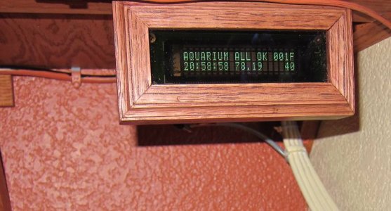
Quick picture of the display.
It is attached to the bottom of the TV shelf, next to tank.

General Status.
Time
Temp
And some hex codes on relays and sensors.

Those cables are for the TV. The display cable is tiny.
 

Attachments

  • display.jpg
    display.jpg
    65.7 KB · Views: 1
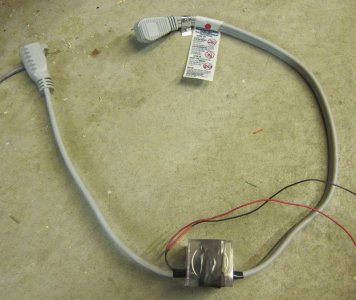
Power cable pic.

The heater and lights draw too much power.
So what I did was put a heavy duty relay in a small acrylic box,
and spliced it into a heavy duty extension cord.

The nice thing about this specific cord is that it was
easy to determine the "hot" line.
 

Attachments

  • pwr_cbl.jpg
    pwr_cbl.jpg
    80.7 KB · Views: 1
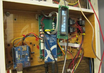
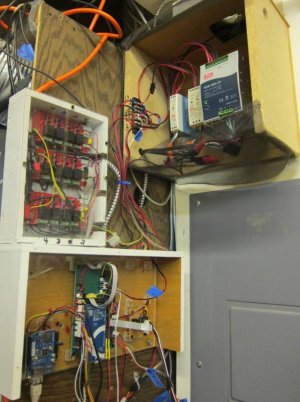
The main electronics:

Here is a picture of all the guts.

Upper left = relay boards.
Lower left = ethernet board, main arduino, and buffer.
Upper right = 5V supply, 12V supply, and big 24V supply.
(The big supply is for the tank LEDs)

It may look a bit like a hazard, but all the 120V is pretty protected.
Armor cable, plexi covers.
 

Attachments

  • main_elec.jpg
    main_elec.jpg
    70.6 KB · Views: 1
just tested something new, if you put the relays high in your setup, the relays will do about a 1/4sec blink on startup. that is about as fast as I can make it go though.
 
Back
Top