DIY PAR meter

mcgyvr

New member
Anyone made one? I'm about to start and was just looking to see if anyone has already been down the road and might let me know any issues/roadblocks/bad sensors/issues they have had.
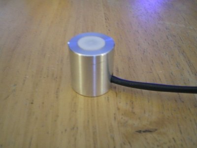
Right now with my current plan I'm looking at about $5 in electronics parts and a waterproof housing of some sort.

I will need someone with a real PAR meter to either let me borrow or I will send my sensor to them when its complete just to take readings and see how accurate and if any additional scaling is needed.
My plans are to make the sensor just hook up to a typical multimeter and the sensor would have a 0-5V output that can easily be read by the meter.
I'm looking at a 2000 micromoles per second per square meter upper limit so .0025V=1 micromoles per second per square meter
 
You are going to have a hard time getting predictable results. While you can cobble together a sensor and diffuser, their interaction is not going to be anywhere near linear. Building a "correction" look-up table to translate the meter results is already a given, but the problem is that your DIY sensor is will likely need a diffrent table for each different bulb spectrum and will still have a lot of error in it.

The diffuser is very important for correcting cosine error and without a lot of trial and error, you going to need a lot of correction. Correction could be done via software loaded into a PC or microcontroller, but the DIY sensor is going to still be the gotcha.

Even buying an OEM sensor (what I have done for my project) has its hurdles. I still have use software to correct the raw sensor values before displaying useable results.
 
Points noted... Thanks.
I plan to use GaAsP photodiodes which require far less cosine correction as their angular response is far more linear than Si photodiodes. Not to mention I'm not using this in an external environment with dawn to dusk light angles nor do I need lab grade results.

I just can't force myself to fork over $299 bucks or whatever it is when I know darn well its only a $2 or less photodiode with an op amps in those Apogee units (which are far from lab grade anyways). Not to mention I think alot of users would be interested in an easy/cheap DIY solution that gives you usable PAR readings.

Heck yeah we'd be interested! A cheap reliable PAR meter would be the holy grail of this hobby (along with cheap lighting).
 
The DIYers on RC are da bomb. Seriously I didn't know this underworld of reef tinkerers existed...building controllers and stuff. Its awesome! Someone smarter than me will have to figure this one out but I will support in any way I can. I don't understand circuits fully (yet), but it is my new hobby to learn.
 
You are going to have a hard time getting predictable results. While you can cobble together a sensor and diffuser, their interaction is not going to be anywhere near linear. Building a "correction" look-up table to translate the meter results is already a given, but the problem is that your DIY sensor is will likely need a diffrent table for each different bulb spectrum and will still have a lot of error in it.

The diffuser is very important for correcting cosine error and without a lot of trial and error, you going to need a lot of correction. Correction could be done via software loaded into a PC or microcontroller, but the DIY sensor is going to still be the gotcha.

Even buying an OEM sensor (what I have done for my project) has its hurdles. I still have use software to correct the raw sensor values before displaying useable results.

So how do store bought PAR meters not need a table or software to correct for their results?
 
I am sure it is doable i know i would try....I just dont have a spare par meter laying around to tear apart to see what makes it tick.
 
Electronic parts have been ordered ($8 total)..should be here in a day or so
Just need to order the parts for the mechanical enclosure which should also arrive in the next day or so..
Hopefully I will have a working prototype this weekend to start playing with.
 
Interested, watching and reading carefully...

aside: I've got to say, from an electronics pov, RC is better than College. I have more practical examples here than I can follow. Awesome.
 
So how do store bought PAR meters not need a table or software to correct for their results?

they actually do have correction built into their onboard software, for example the commonly used apogee mq-200 only measures between 360 and 670 nm spectrum, and has a couple different settings based on "expected" type of light. The closest thing to our aquarium light is the "sun" setting, which is good, but it does not lend enough internal correction to the blue spike in most of our lighting thus the advanced LED guys suggesting they should add at least 15% to their PAR readings based on the intense blue spike they give.
 
Not knowing a thing about how they actually work, I would assume that a PAR meter cannot actually distinguish between wavelengths of light that hits it, and instead employs a light filter on top of the sensor that will block out light that is outside of the 360 to 670 region. Does that sound about right?
 
Not knowing a thing about how they actually work, I would assume that a PAR meter cannot actually distinguish between wavelengths of light that hits it, and instead employs a light filter on top of the sensor that will block out light that is outside of the 360 to 670 region. Does that sound about right?

I dont know exactly either, though I would assume its more on what the sensor can "see".. to expand on that, it would be a certain subset of radiation(nm) excites certain somethings within the sensor which generate voltage, that is translated through a table then some sort of weight-based calculation of known photosynthetic wavelength ranges.

....but I could be WAAAAAYYYY off :strooper:

edit: here's some basic info on photodiodes http://en.wikipedia.org/wiki/Photodiode
 
Last edited:
The photodiodes typically have a cover/BG filter that blocks UV light.
The sensor I'm using has a 400nm to 700nm spectral range with max sensitivity at 550nm.
I just finished the diffuser. It's a 1mm thick 3/8" dia teflon disc. Turned it on the lathe at work. Ran it really slow so I have very good surface finish.
 
Not knowing a thing about how they actually work, I would assume that a PAR meter cannot actually distinguish between wavelengths of light that hits it, and instead employs a light filter on top of the sensor that will block out light that is outside of the 360 to 670 region. Does that sound about right?

Pretty much, coupled with tuned sensitivity on the substrate its self.

To the person building it, which part number diode did you use? Whats your amplification strategy?

I have an Apogee sensor here (not with the overpriced multimeter though), so we can do some comparison readings. I have some MH, LED and T5s amongst various setups.
 
I'll publish the parts list/schematic information when it is completed... (once I'm done and satisfied with the results).

I will take you up on your offer about comparing it with the Apogee sensor though. Once its completed.. (tracking info now says I won't have the electrical parts till monday..boo hoo)
 
Teaser pic.. body and diffuser. Just gonna paint it black.
 

Attachments

  • DIY Par Sensor.jpg
    DIY Par Sensor.jpg
    76.4 KB · Views: 17
This is gonna be SWEET! I can't wait to see what you come up with and the final results. Pics pics and more pics please, as you go along. I'm just a dumb fireman, but I can follow pics and a good description. :lol:
 
Back
Top