aleithol
New member
I'm in process of designing a new 150 gallon reef tank and would greatly appreciate more eyes on what I think I want to do after trying to research this as much as possible by myself. If you're into detail and up for a challenge, please read on"¦
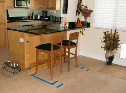
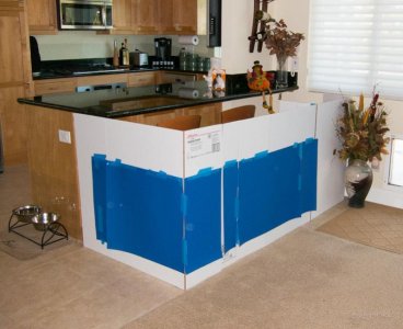
A key difference making this a non-traditional setup from most examples I can find is that the bottom of my sump must be on the same level as the tank itself "” not underneath. The tank will be located in my family room only a few inches off the floor with the back 6" pushed under the lip of an existing granite bar that is the separator into my kitchen. I'll have 6" behind the tank for plumbing, but the center and rear right half in the back won't be accessible once the tank is positioned. I have another couple of feet I can use to house a sump on the right end of the tank. All will be enclosed in a custom cabinet with removable hood to match my existing cabinetry. The attachments have a picture of the "œbefore" as the area looks now, and a mock-up of where the cabinetry will be (blue would roughly be the visible area of the tank after the top and bottom cabinet lips are in place. The right side white area is where the sump will be located.
Attachments:
"150G Reef - Scouting Locations" is where the tank will be located.
"150G Reef - Mock Up" is roughly the visible area of the tank in blue, with white cardboard being the new cabinetry surround. The far area of white behind the plants sitting on the tile floor is where the sump area will be.
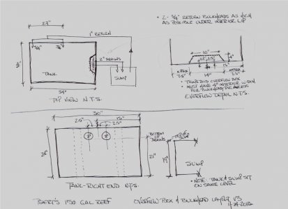
"AEL Reef Plumbing Diagrams V2" are referenced below to try and put a picture with the words. Sorry for hand drawn pictures, but hopefully they help.
PART I - SIZING & CONCEPT
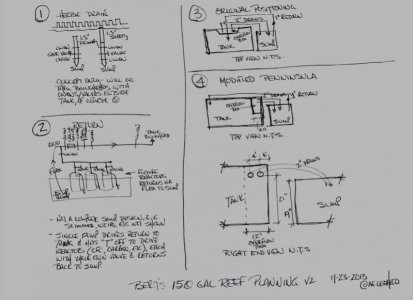
My initial drain and return plumbing concept is shown in Diagram #1 & 2 of the 3rd attachment
Calculations
TANK 54" L x 30" W x 24" H "” approx 168 gallons
"” water volume less, of course, rockwork and sand displacement
SUMP 30" L x 18" W x 19" H "” approx 44 gallons MAX
"” Assuming at normal operating volume the water level is at 10", the sump will contain approx 23 gallons
"” If I assume the following tank water height above the lowest overflow point:
--"” 1" = 7 gallons
--"” 2" = 14 gallons
--"” 3" = 21 gallons (which is far more than could get into the overflow)
"” Therefore, 23 gallons + 21 gallons MAX = 44 gallons which just fits in the 44 gallon sump
Note: I believe this is a bit conservative as the water volume in the tank will be a bit less because of the overflow box and rock work, but there will be a little water in the lines that may not be accounted for, and yes, available volume in the sump will be a bit less because of things like weirs, socks, skimmer, pump that displace water "¦hopefully all roughly offsetting one another. "¦but the real thing is, the top of the overflow box where the teeth begin is going to ensure the tank water height is maintained above the drain height, so I should be fine without worry about water on the floor (assuming my plumbing does not leak") ).
).
If I estimate 3-5X/hour water TURNOVER required through the sump:
"” 168+23 = 191 total water in the system
"” 191x3 = 573 gallons/hr Recommended drain/overflow .99" with 9" linear overflow
"” 191x5 = 955 gallons/hr Recommended drain/overflow 1.28" with 14" linear overflow
I'll need to then take into consideration head pressure (and use of return for T'd-off reactors) when sizing the in-sump pump
SO"¦ It would appear"¦
1) Using dual 1.5" drains allows the 3-5 turnover rate, as well as desired redundancy
2) Planned sump should provide sufficient capacity to avoid tank overflow when the pump is off
3) I assume a single 1" return is sufficient from the sump pump to the tank, but have been unable to find how to calculate/validate this
4) I plan to use glued slip joints on all PVC connections, with exception of the ones going direction into the bulkheads from outside the tank which will be screw-type
5) I'd like to use a single (larger) pump for the return and to drive the (GFO, carbon) reactors off a T at the same time, but have read in at least one place I may regret that if I run the Herbie drain as I'll have to keep adjusting the drain flow as I change things off the T. Thoughts? (I'm not hung up having to use the Herbie thing, just like the idea of having built in redundancy.)
6) Do you see any problems with the design, and can you offer a better alternative?
PART 2 "” WHERE TO DRILL THE HOLES
Original (Trapazoid overflow in center of tank back)
See Diagram #3
"” Concern maintaining plumbing at back of tank given accessibility issues
-- I've tossed out this idea in lieu of Alternative 1
Alternative 1: Modified Peninsula (Rectangular overflow in right back corner)
See Diagram #4
"” Easy access to drains on right side of tank through sump area, and it's a short run right next to the sump
"” Easy access to the return running into the left back upper corner of tank, with a straight run of PVC in the area hardest to otherwise reach behind the tank
"” PVC Bulkhead / Elbow Dimensions
--"” 2" 90-deg elbow needs ~3 1/2" for installation (~2 5/8" after inserted)
--"” Bulkhead for 2" requires ~3 1/4" for installation; leaves <3/4" inside tank after installed (gasket+nut); "œNut" inside tank is ~4.25" around
"” Overflow Box
--"” Need min 9" - 14" linear overflow based on turnover rate
--"” Internal size must allow access for new bulkhead installation and 2" 90-deg installation
--"” Min overflow box of 9.5" L x 4 1/4" W (from back of tank)
--"” FINAL SIZE TO BE 12" L x 4.5"W, positioned inside right rear corner of tank (provides 16.5" linear overflow, enough room to install "œU" shaped double elbows inside box, or ability to replace bulkheads)
--"” Current plan is to use "œHerbie Style" returns, but durso or stockman are alternatives. We don't need to get into the debate of which is better again here (I've read dozens of threads), unless I'm missing something I'm going to regret!
"” 1" Return to left side tank rear
--"” Will have check valve in return run as secondary safety net, and yes, I know it will need to be maintained
"” Tank Drain Holes
--"” FINAL POSITION to be with bottom of holes 21" from bottom of tank; Center 4" & 8" from tank bank
--"” Need to keep drain line to sump lower than tank
--"” Top of sump is 19" H
--"” Note: That's only a 2" vertical drop over a couple of lateral feet almost directly into the sump
SO"¦ It would appear
1) The modified peninsula location of the overflow box is a superior solution
2) It will require attention with powerbeads to ensure flow and debris removal
3) Is it an issue having only minimal drop from the physical hole on the tank to the sump? ...I don't think so, but would appreciate confirmation so I stop talking to myself about this!
THANK YOU to anyone that has read this far. I would appreciate confirmation if you believe this will work, or if you see any major issues or have recommendations, a special pat on the back for your help! I've not included plans on lighting and rest of the infrastructure here "” another time, another thread perhaps.
A key difference making this a non-traditional setup from most examples I can find is that the bottom of my sump must be on the same level as the tank itself "” not underneath. The tank will be located in my family room only a few inches off the floor with the back 6" pushed under the lip of an existing granite bar that is the separator into my kitchen. I'll have 6" behind the tank for plumbing, but the center and rear right half in the back won't be accessible once the tank is positioned. I have another couple of feet I can use to house a sump on the right end of the tank. All will be enclosed in a custom cabinet with removable hood to match my existing cabinetry. The attachments have a picture of the "œbefore" as the area looks now, and a mock-up of where the cabinetry will be (blue would roughly be the visible area of the tank after the top and bottom cabinet lips are in place. The right side white area is where the sump will be located.
Attachments:
"150G Reef - Scouting Locations" is where the tank will be located.
"150G Reef - Mock Up" is roughly the visible area of the tank in blue, with white cardboard being the new cabinetry surround. The far area of white behind the plants sitting on the tile floor is where the sump area will be.
"AEL Reef Plumbing Diagrams V2" are referenced below to try and put a picture with the words. Sorry for hand drawn pictures, but hopefully they help.
PART I - SIZING & CONCEPT
My initial drain and return plumbing concept is shown in Diagram #1 & 2 of the 3rd attachment
Calculations
TANK 54" L x 30" W x 24" H "” approx 168 gallons
"” water volume less, of course, rockwork and sand displacement
SUMP 30" L x 18" W x 19" H "” approx 44 gallons MAX
"” Assuming at normal operating volume the water level is at 10", the sump will contain approx 23 gallons
"” If I assume the following tank water height above the lowest overflow point:
--"” 1" = 7 gallons
--"” 2" = 14 gallons
--"” 3" = 21 gallons (which is far more than could get into the overflow)
"” Therefore, 23 gallons + 21 gallons MAX = 44 gallons which just fits in the 44 gallon sump
Note: I believe this is a bit conservative as the water volume in the tank will be a bit less because of the overflow box and rock work, but there will be a little water in the lines that may not be accounted for, and yes, available volume in the sump will be a bit less because of things like weirs, socks, skimmer, pump that displace water "¦hopefully all roughly offsetting one another. "¦but the real thing is, the top of the overflow box where the teeth begin is going to ensure the tank water height is maintained above the drain height, so I should be fine without worry about water on the floor (assuming my plumbing does not leak
).If I estimate 3-5X/hour water TURNOVER required through the sump:
"” 168+23 = 191 total water in the system
"” 191x3 = 573 gallons/hr Recommended drain/overflow .99" with 9" linear overflow
"” 191x5 = 955 gallons/hr Recommended drain/overflow 1.28" with 14" linear overflow
I'll need to then take into consideration head pressure (and use of return for T'd-off reactors) when sizing the in-sump pump
SO"¦ It would appear"¦
1) Using dual 1.5" drains allows the 3-5 turnover rate, as well as desired redundancy
2) Planned sump should provide sufficient capacity to avoid tank overflow when the pump is off
3) I assume a single 1" return is sufficient from the sump pump to the tank, but have been unable to find how to calculate/validate this
4) I plan to use glued slip joints on all PVC connections, with exception of the ones going direction into the bulkheads from outside the tank which will be screw-type
5) I'd like to use a single (larger) pump for the return and to drive the (GFO, carbon) reactors off a T at the same time, but have read in at least one place I may regret that if I run the Herbie drain as I'll have to keep adjusting the drain flow as I change things off the T. Thoughts? (I'm not hung up having to use the Herbie thing, just like the idea of having built in redundancy.)
6) Do you see any problems with the design, and can you offer a better alternative?
PART 2 "” WHERE TO DRILL THE HOLES
Original (Trapazoid overflow in center of tank back)
See Diagram #3
"” Concern maintaining plumbing at back of tank given accessibility issues
-- I've tossed out this idea in lieu of Alternative 1
Alternative 1: Modified Peninsula (Rectangular overflow in right back corner)
See Diagram #4
"” Easy access to drains on right side of tank through sump area, and it's a short run right next to the sump
"” Easy access to the return running into the left back upper corner of tank, with a straight run of PVC in the area hardest to otherwise reach behind the tank
"” PVC Bulkhead / Elbow Dimensions
--"” 2" 90-deg elbow needs ~3 1/2" for installation (~2 5/8" after inserted)
--"” Bulkhead for 2" requires ~3 1/4" for installation; leaves <3/4" inside tank after installed (gasket+nut); "œNut" inside tank is ~4.25" around
"” Overflow Box
--"” Need min 9" - 14" linear overflow based on turnover rate
--"” Internal size must allow access for new bulkhead installation and 2" 90-deg installation
--"” Min overflow box of 9.5" L x 4 1/4" W (from back of tank)
--"” FINAL SIZE TO BE 12" L x 4.5"W, positioned inside right rear corner of tank (provides 16.5" linear overflow, enough room to install "œU" shaped double elbows inside box, or ability to replace bulkheads)
--"” Current plan is to use "œHerbie Style" returns, but durso or stockman are alternatives. We don't need to get into the debate of which is better again here (I've read dozens of threads), unless I'm missing something I'm going to regret!
"” 1" Return to left side tank rear
--"” Will have check valve in return run as secondary safety net, and yes, I know it will need to be maintained
"” Tank Drain Holes
--"” FINAL POSITION to be with bottom of holes 21" from bottom of tank; Center 4" & 8" from tank bank
--"” Need to keep drain line to sump lower than tank
--"” Top of sump is 19" H
--"” Note: That's only a 2" vertical drop over a couple of lateral feet almost directly into the sump
SO"¦ It would appear
1) The modified peninsula location of the overflow box is a superior solution
2) It will require attention with powerbeads to ensure flow and debris removal
3) Is it an issue having only minimal drop from the physical hole on the tank to the sump? ...I don't think so, but would appreciate confirmation so I stop talking to myself about this!
THANK YOU to anyone that has read this far. I would appreciate confirmation if you believe this will work, or if you see any major issues or have recommendations, a special pat on the back for your help! I've not included plans on lighting and rest of the infrastructure here "” another time, another thread perhaps.
")