BeanAnimal
Premium Member
DISCLAIMER - THESE ARE NOT PLANS. DON'T MODIFY THINGS THAT YOU DON'T FULLY (100% FULLY WITHOUT QUESTION) UNDERSTAND. FOLLOW ALONG TO SEE EXACTLY WHY!!!!
JBJ Arctica Chillers have a +/- 1 degree Fahrenheit hysteresis. That means that if the chiller is set to 77 degrees, it will start chilling at 78 and stp chilling at 76. That is a 2 degree swing. In the case of my tank, even the 1/10 horsepower chiller brings the temperature down in about 30 mins. I do not like the large 2 degree swings throughout the day.
If the chiller is plugged into an external controller, then it fully powers on/off with each cycle. This means that each time chilling is called for, the chiller has to turn on, wait 5 mins (built in timer to prevent short cycling) and then chill. It also means that the internal controller must be set low enough to be always on, so it can't really act as a fail-safe. Lastly, the display (obviously) is dead when the chiller has no power.
My solution is to bypass the internal relay, and substitute a relay controlled by my Profilux controller where I can set hysteresis to as low as +/- .135 degrees.
Here is the published schematic for the JBJ 1/10

Simple enough - Cut the "white" wire and put a relay (controlled by the Profilux) between it and the SKY wire. Might as well add a DPTD switch to be able to switch between "internal" and "external" control too...

Pretty straight forward right? In one position the switch takes the internal controller's output OUT of the circuit and in the other position it takes the NEW relay out of the circuit and restore the connection to the internal control. Notice on BOTH position, the internal display of the chiller is still powered!
There are other ways that this could be done... allowing both to operate at the same time (below) or have them in series, etc. The problem is that operational modes would be confusing. In the schematic below the control would be "external only" or "both" depending on switch position. I opted against his (again it os confusing).

SO EASY ENOUGH RIGHT???? NOT SO FAST!!
*****THE SCHEMATIC PUBLISHED BY THE MANUFACTURER FOR THIS MODEL DOES NOT MATCH WHAT IS INSIDE OF THE CASE*****
In most devices, best practice is to always switch the "hot" leg and NOT the "neutral" leg. In fact, the schematic above, shows the hot leg (SKY) traveling to the "controller" and being returned (WHITE) as switched to the compressor and fan. It shows the NEUTRAL wire (BROWN) being tied directly to the compressor and fan, as well it shows the FUSE on the line/hot (SKY) wire (where it should be). The reasoning is simple. When the device is OFF or the fuse is blown, one would expect no live (hot) power to the components that are not ON.
Upon disassembling the chiller to install my modifications, I quickly realized that the FUSE was on the BROWN (NEUTRAL) wire and that the SKY (LINE/HOT) wire was tied directly to the compressor and fan and then fed to the 4 pin plug that powers the display. THEREFORE, the "WHITE" wire coming from the controller and display module that is the "switched" line is actually NEUTRAL. That means that even with the compressor and fan are not running, or in the case of a blown fuse) that live 120V power is present throughout the device. This is insanity... but without rewiring the entire device and modifying the on-board controller, can't be "fixed". I will reach out to JBJ at some point, but would venture to say that they don't know or care, as these are not likely "designed" in-house.
The actual schematic and my modifications are show below.


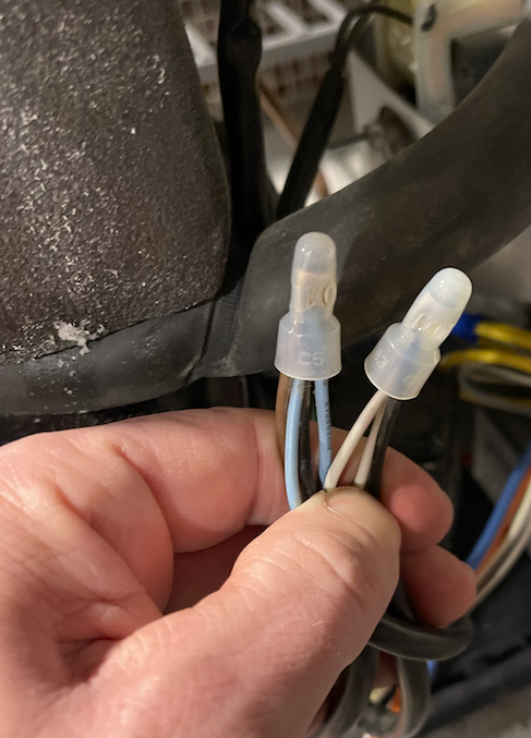
Left factory connection shows SKY coming from the power cord, going out to the 4 pin connector AND connecting to the compressor (brown) and fan (black).
Right factory connection shows WHITE coming from the 4 pin connector and going to the compressor (white) and fan (black).
The is exactly opposite (left connector) of what the factory schematic shows!
Not show (brown from power inlet) goes directly to the 4 pin connector. The left connector was left in-tact and the right connector is the one that I cut, placing the switch in between.

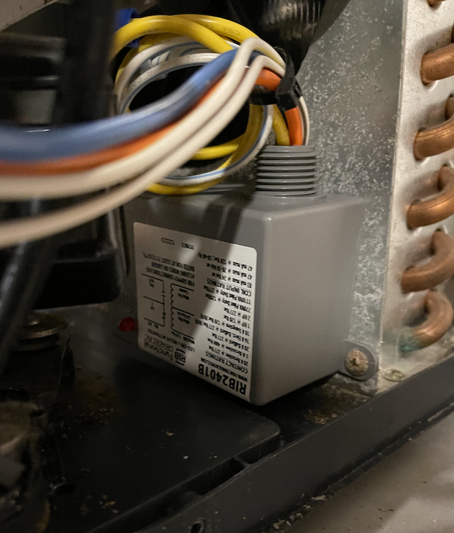
The photo below shows the relay installed. I used an existing screw on the condenser case.

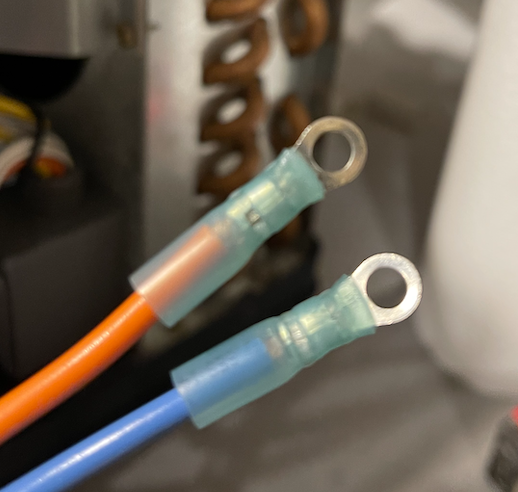
Waterproof ring terminals crimped (below) before heat shrinking. These will connect to the terminals of the DPDT switch. A note here, you MUST use a ratcheting or commercial grade crimper. Using a pair of pliers or cheap "crimper" never results in a reliable termination.

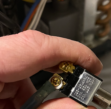
120V 15A DPDT toggle switch show n with one terminal connected.

JBJ Arctica Chillers have a +/- 1 degree Fahrenheit hysteresis. That means that if the chiller is set to 77 degrees, it will start chilling at 78 and stp chilling at 76. That is a 2 degree swing. In the case of my tank, even the 1/10 horsepower chiller brings the temperature down in about 30 mins. I do not like the large 2 degree swings throughout the day.
If the chiller is plugged into an external controller, then it fully powers on/off with each cycle. This means that each time chilling is called for, the chiller has to turn on, wait 5 mins (built in timer to prevent short cycling) and then chill. It also means that the internal controller must be set low enough to be always on, so it can't really act as a fail-safe. Lastly, the display (obviously) is dead when the chiller has no power.
My solution is to bypass the internal relay, and substitute a relay controlled by my Profilux controller where I can set hysteresis to as low as +/- .135 degrees.
Here is the published schematic for the JBJ 1/10
Simple enough - Cut the "white" wire and put a relay (controlled by the Profilux) between it and the SKY wire. Might as well add a DPTD switch to be able to switch between "internal" and "external" control too...
Pretty straight forward right? In one position the switch takes the internal controller's output OUT of the circuit and in the other position it takes the NEW relay out of the circuit and restore the connection to the internal control. Notice on BOTH position, the internal display of the chiller is still powered!
There are other ways that this could be done... allowing both to operate at the same time (below) or have them in series, etc. The problem is that operational modes would be confusing. In the schematic below the control would be "external only" or "both" depending on switch position. I opted against his (again it os confusing).
SO EASY ENOUGH RIGHT???? NOT SO FAST!!
*****THE SCHEMATIC PUBLISHED BY THE MANUFACTURER FOR THIS MODEL DOES NOT MATCH WHAT IS INSIDE OF THE CASE*****
In most devices, best practice is to always switch the "hot" leg and NOT the "neutral" leg. In fact, the schematic above, shows the hot leg (SKY) traveling to the "controller" and being returned (WHITE) as switched to the compressor and fan. It shows the NEUTRAL wire (BROWN) being tied directly to the compressor and fan, as well it shows the FUSE on the line/hot (SKY) wire (where it should be). The reasoning is simple. When the device is OFF or the fuse is blown, one would expect no live (hot) power to the components that are not ON.
Upon disassembling the chiller to install my modifications, I quickly realized that the FUSE was on the BROWN (NEUTRAL) wire and that the SKY (LINE/HOT) wire was tied directly to the compressor and fan and then fed to the 4 pin plug that powers the display. THEREFORE, the "WHITE" wire coming from the controller and display module that is the "switched" line is actually NEUTRAL. That means that even with the compressor and fan are not running, or in the case of a blown fuse) that live 120V power is present throughout the device. This is insanity... but without rewiring the entire device and modifying the on-board controller, can't be "fixed". I will reach out to JBJ at some point, but would venture to say that they don't know or care, as these are not likely "designed" in-house.
The actual schematic and my modifications are show below.
Left factory connection shows SKY coming from the power cord, going out to the 4 pin connector AND connecting to the compressor (brown) and fan (black).
Right factory connection shows WHITE coming from the 4 pin connector and going to the compressor (white) and fan (black).
The is exactly opposite (left connector) of what the factory schematic shows!
Not show (brown from power inlet) goes directly to the 4 pin connector. The left connector was left in-tact and the right connector is the one that I cut, placing the switch in between.
The photo below shows the relay installed. I used an existing screw on the condenser case.
Waterproof ring terminals crimped (below) before heat shrinking. These will connect to the terminals of the DPDT switch. A note here, you MUST use a ratcheting or commercial grade crimper. Using a pair of pliers or cheap "crimper" never results in a reliable termination.
120V 15A DPDT toggle switch show n with one terminal connected.
Last edited:
