Low voltage DIY ATO, need advice...

LatinP

Member
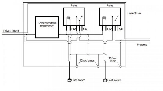
So after spending 90 dollars on an ato less than a year ago and having that go on me I decided I want to make my own. I looked at the current options from autotopoff.com and aquahub, I don't really like either of the designs since I'll have to customize for my application once I get the wiring done. I also want more than one relay for redundancy.

I'm currently looking at different relays on e-bay to see what can be done. I plan on powering the relays with 12v chargers which I happen to have plenty lying around doing nothing.

I'm looking for the right relay to get, I'm no professional electrician but I'm pretty handy. My question is would 2 of these relays work for our application, and if not would anyone know of a better relay to use? I'd prefer to stay away from solid state since they'll be powered by aqualifters and SSRs have a minimum load requirement sometimes. I'd also prefer something that comes with a socket just for ease of use.

These are the relays I'm looking at the moment:
http://www.ebay.com/itm/2-LOT-TEMCo...562?pt=LH_DefaultDomain_0&hash=item418c39541a

If those would work or if someone knows of something better please let me know, thanks for reading!
 
If going for low wattage, why not use a 12V DC pump as well, and do away with relays completely, as well as only needing one power supply?

Tim
 
Here's my wiring diagram I'm using to build my own. 12volt float side, 110volt pump side, two relays and two floats and lights to tell you what's going on for a little bling. Just rounded up all the parts. I was going to post the build once I was finished with it.
 

Attachments

  • ATO 12v wiring diagram with lights 2.jpg
    ATO 12v wiring diagram with lights 2.jpg
    34.3 KB · Views: 6
If going for low wattage, why not use a 12V DC pump as well, and do away with relays completely, as well as only needing one power supply?

Tim

The float switches can't handle the amount of amperage a DC pump would pull. They can only handle about .5 amps. You still would have to have a relay setup. Unless you are using a very small pump and then it would only pump a very short distance.

skeeter
 
Here's my wiring diagram I'm using to build my own. 12volt float side, 110volt pump side, two relays and two floats and lights to tell you what's going on for a little bling. Just rounded up all the parts. I was going to post the build once I was finished with it.

I have seen this schematic before, and had the same thoughts on it at that time, but really did not get involved in it. Since this schematic is popping up again, I think this circuit needs a closer look taken, and some better information about redundancy for the system.

The system does include a "redundant" relay, thus protecting the system against running, or a "failed close" scenario which would dilute the system water, and quite possibly cause a flood. The odds against two relays (or switches) failing closed, are rather high, made much higher by the failure probabilities of relays in general.

However, is the system more reliable? Inherently, no. The added complexity, makes the system less reliable. There are more parts that can fail, and the odds of multiple failures simultaneously does increase. Since failure of a mechanical device (relay, switch) is based on age, number of cycles, mechanical wear and tear, it is more likely that two of the same item of the same "age" are close to failure, even if only one of them actually fails.

Ok, so what? There are two main reasons that mechanical relays fail. Contamination (solder, flux, and numerous et al) is a major cause of early failures, and mechanical wear of internal switching components is also a major cause. The life expectancy is determined by the useful life of the contacts.

OK, so what? Well this design only addresses two of three failure modes for relays. The three are: short (failed closed,) spurious trip (failure of control/monitoring circuitry—broken float switch contacts) or failure to trip (fail open.) The statistical probability of a "fail closed" is ~19%, a "spurious trip" is 26%, and a "fail open" is 55%. E.G. it is highly more likely that a single component failure will cause the system NOT TO RUN, than it is that the system will fail closed, and continue to run. Given the statistical probabilities, the more reliable system would have parallel redundancy, to insure it actually runs, rather than series redundancy, to insure that it shuts off. Realistically, for a safe system, you need both, which adds more complexity (4 relays and 4 switches) and overall less reliability (it depends though.) Incidentally, a fail open can cause the return pump to run dry (if left unnoticed) and this can and does cause damage to the pump impeller/volute. Pick your poison.

Also the illustrated circuit does not have flyback diodes. These are diodes used to eliminate flyback, which is the sudden voltage spike seen across an inductive load when its supply voltage is suddenly reduced or removed. The "flyback" can damage the relay, adding an additional cause for it to "fail open."

It would only be logical to use a circuit that is inherently more reliable (less moving parts than the above, and industry standard for this type of application) called a latching circuit. One switch sets a latch, and it runs till another switch breaks the latch. 2 switches, 1 relay; for redundancy use strictly mechanical (no electricity) means to fail safe, preventing the feast or famine. Though it cannot hurt to have both high and low electrical cutoffs for the ATO pump and return pump, respectively, in addition to your mechanical fail safes.

ATOs, simply, are not as simple to do safely than folks would wish.
 
Just solder the switch in to any wall 12 dc transformer, I had a ton laying around from old chargers and stuff. and then run the guy I mention before in series with the switch. ATO for under 40 bucks!
 
Thank you Uncle,
For that in depth analyzes of my ATO wiring diagram. It is true that it is not prefect but it is designed, with my simple mind, to do exactly what I want it to do. I want it to add top-off when needed but have a very very slim chance(3%)of failing in the on position and overflowing my sump. Dual float and dual relays do that. I would prefer it to fail, when it does, in the open position and not add anything to my sump. I check my sump almost daily and would notice a low sump level way before it becomes any problem.

P.S. I calculated the 3% possibility of both relays failing closed by pulling it out of my arse. Sorry I couldn't pass it up. :)

skeeter

Well I am sure you have it all figured out, and that is good. :) However, there are many that do not have it figured out, are not as "attentive" as you are, or would like to the leave the house on vacation for a week or more. So they ask questions, concerning circuitry, redundancy, and safety.

They may be more interested in a larger view of the topic, than just what you want for your system. A view of not only what the circuit design shown will do, but also what it will not do, and how it addresses the least likely failure mode, but not the most likely. Many do not give much thought to possible consequences of the pump running dry; many do not completely understand the concepts of redundancy and fail safe.

The thread was addressing "what relays" but was not going much further than that, and the OP specifically mentioned redundancy. The OP, and anyone else interested in education, now has usable information, that they can explore further, if they wish.

I appreciate the "jabbing humor" and I do see it for what it is... but you really did not need to make up a number, you could have looked it up, and/or done the math. I do, even when I have been through a topic a hundred times. :)

http://www.google.com/url?sa=t&rct=...qavcL_s-YibR0Zw&bvm=bv.83829542,d.eXY&cad=rja

http://www.navsea.navy.mil/nswc/crane/sd18/Public Documents/ProductArchive/Relays.pdf
 
Back
Top