knabbuziak
New member
Hi everyone! This is my first post here so I shall try to make it a good one! 
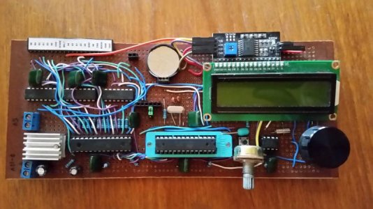
I've made an Arduino-based LED light controller that first was meant to be a product for our company. However, I'm not a great salesman, so we never sold any, but I still think that it is a useful piece of equipment and I've always loved the open community, so I'm now releasing it to the public.
I've tried as far as possible to only use easy-to-get and easy-to-solder components such as:
- Atmega328P-PU with crystals
- TexasInstruments TLC5940
- 74HC04
- RTC1307
- 16x2 LCD with 44780 interface
The controller is capable of dimming 12 channels of high power LED's via MeanWell LDD-drivers in 4096 steps of intensity (12 bits).
I've also added temperature controll to controll fans and shut of the LED's if the heatsink is too hot.
A separate channel to dim the Moonlight
Since I'm from Sweden, I wrote all comments in the code in Swedish, so I'm currently working on the translation and optimization of the circuit.
I've put one computer in my co-owners own DT at his house, and it has been working perfectly for the last two years.
In the future I hope to expand it with pump control, lunar phace and tide simulation etc.
The picture is of my lab-computer that I've only used for testing, but my colleagues computer is very similar.
I also have a code for a much more simple comuter without the TLC if anyone is interested. I managed to build it on a very small board integrated into a Juwel 54L lid.
If anyone has suggestions on how to make it better, please let me know! I will try to update and translate the codes and get back soon with wiring diagrams etc.
I hope this will be useful for someone!
I've attached the code (messy), some of the libraries (the ones that I don't think is included in the arduino IDE) and a picture of my testing computer.
If I manage to get the scetch right, I will try to order a few machined PCB's
")


