https://photos.google.com/search/_tra_/photo/AF1QipOKL3FfVpCUnNhvM5Leb7TScBzsmChcAsG-LKUI
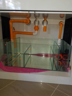
How does this look ...
Core pump only @20% like to get more flow in the tank but if I crank the core pump up I'm worried the sump return will flood...
I can't see the photo for some reason. Your 1" full siphon should be able to handle 2000 gph+ based on information from BeanAnimal's web site.
http://www.beananimal.com/articles/hydraulics-for-the-aquarist.aspx
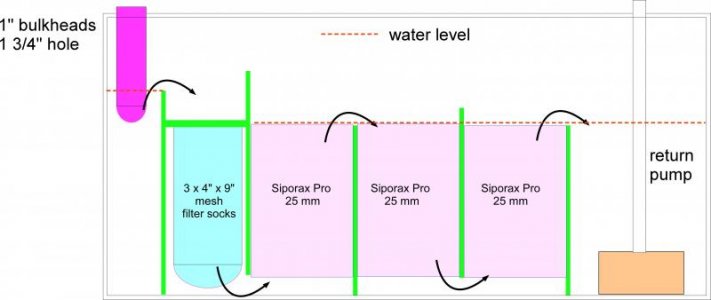
I am assuming here 1" pipe, full siphon, 4' drop from the overflow level to the water level in the sump.
Your pump, running at 100% and assuming 5' of head from the bottom of the sump to the inlet should move around 1500 gph
https://www.bulkreefsupply.com/cor-20-intelligent-return-pump-neptune-systems.html
Adjust these assumptions to match your tank, but they should be close. Therefore, unless the intended water level in your sump is quite high, I don't see how you will easily overflow the return or the sump with this configuration.
I'd open the gate valve on the full siphon fully and crank up your return pump, paying careful attention to the water level in both the overflow and the sump. Obviously, if it looks like you will flood the overflow, back off the flow or shut it down. Set the return pump power such that you have as much flow running back into the tank as you want, then adjust the gate valve on the full siphon so that you get some water coming through the open channel. I like my water level to be about half way up the elbow of the open channel. Neither of my pumps can keep up with the capacity of the full siphon when the gate valve is all the way open.
I set return pipe entry into the tank height so that when the power is off, the maximum amount of water to be returned to the sump still leaves some gallons of extra capacity. For me, this is a safer approach than relying on a valve to prevent backflow down the return to the sump when power is off...
Having said all that, I would not use the return pump to produce the desired flow in the tank. That is what powerheads are for. You should plan to run 5-10x the tank volume through the sump per hour.