redtop's Ferduino controller

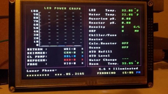
Guys, with the help of Fernando, and along with the development and english conversions by willi and redtop, I have set up the ferduino controller without any ancilliary parts connected.

Just an elecfreaks LCD/SD/TOUCH shield, the Sainsmart TFT LCD 5.0", and a clone mega2560.

Nothing else is connected, and it is all working fine. So I just wanted to thank WIlli and Redtop for your most excellent contributions good sirs!:rollface:

I am so stoked!

I havent even baught a reef tank yet, so you could say I am building it exclusively around the Ferduino.

I only need to make a few changes to the code, the main one being to have some failsafe to make sure ATO does not happen until my proposed herbie overflow has stabilised and created 100% syphon. (with a little running into emergency of course), If I cant code this into the ferduino then I will use an UNO to control power to the mega after a power out, which will only power up the ferduino once the syphon is correct therefore the sump return level will be correct.

I also will be using stepper motors, so that will either be coded in, or the outputs of the mega will once again go to the aforementioned UNO, which will convert duration of the ferduino into rotations on a stepper motor.

The peristaltic pumps I have from a planted tank controller I made will be modified to use the small 5v geared stepper motors available all over ebay for arduino projects, they might last, they might not, cheap enough to rebuild, they work with a 2mm shaft so I need shaft adaptors and some way to mount the steppers.

This all of course depends on how good my ability to add additional functionality into the system progresses. Currently I am way to pants to modify the code outright, but I can definately write my additional functionality into an UNO and trigger the UNO via i2c or simple pin triggers..:dance:

One thing is certain as I have already designed and tested working versions, I will soon be making more substantial optical sensors for the water level detection that output the same as the switches but use an optical prism like the Tunze. They feature arduino IR line detectors for robots, housed inside urine sample bottles with the conical base.

I have a vid of the test version if anybody is interested. I will have to upload it to zee tube however.

Anyway. Thank you and Obrigado to everybody involved in this project who have provided me with this excellent code and support.

attachment.php


Jamie.

PS. Can anybody point me towards where I can modify some parameters for the homescreen, such as colour, labels etc, I would like to change 'FERDUINO' to my own name if possible, I cant find it in the code anywhere which makes me think it is a hex value or something, rather than plaintext.
 

Attachments

  • 10624669_631026187014996_2871127128758821660_n.jpg
    10624669_631026187014996_2871127128758821660_n.jpg
    52.9 KB · Views: 15
Last edited:
ohnobrowncow,

with the speed at which the ATO will work, I don't think you'll need to do anything to the code, especially if you have extra space in your sump for the additional few ounces of fresh water that might build up while the overflow is stabilizing....

I don't think you'll have any problems with it as is but that will be something that Fernando might know more about

as for changing the "FERDUINO" text on the home screen, it's easy to do but I'll have to find where to do it again, I'll let you know in a day or 2, I don't have time to look for it right now...right now off the top of my head, I think it is in the inicio tab somewhere near the top

it's looking good on the 5 inch screen :D
 
Well I have typed 101 replies, but one way or another, my phone battery dies, or I accidentally click a bookmark, then away goes everything I typed haha..

I wont go into the waterchange stuff because it requires to much of an explenation of why I realised it might not work with the ATO and herbie. One thing is certain, I will need to do something to ensure no fresh water is pumped in while the sump return level flucuates.

When water syphons it does not need head height, the force is drawing from beneath.
While the emergency takes over until the syphon kicks in fully, the water requires a little head height to break the miniscus around the emergency overflow elbow and to overcome the height required to exceed the emergency overflow point.

This means more water is able to be pumped into the display tank before hitting the height of the emergency, which means a drop in the return section level, this, depending on the display tank size vs sump tank size vs weir size, can mean a couple mm to over an inch.

I stated I am buying a new 220ltr clearseal reef space now, as my first reef tank, but originally I embarked on building a controller to do ATO and AWC, for a 60ltr ADA Amano 60P style clone, which is sat behind me, unpainted, but otherwise quite functional (and I will add, the stand cost me around $40, not over $800, yes, $800 for a 60cm ADA stand)

The weir on that tank was 10cm x 6cm x 6cm.. Very small. The sump was only 18" x 10", the display only 24" x 12".. When I run this and tested it out, the fluctuation in the return was over 1".

It was then, when I realised a Tunze ATO would be useless on a system like this, I realised however an arduino would not, as I could write any condition into the code to be met, such as sensors to tell the arduino when the 'harmony point' was met, the harmony point being the spot where the water level sits in the return section once a 99% syphon 1% emergency overflow has been achieved.

It was very stable after about 1-2 minutes of purging the air.

It is likely I will make another micro overflow even on the proposed reefspace 220lr, as it supped water like no tomorrow, with 3/4inch plumbing, took up minimal display realestate, skimmed the surface very well, and was dead silent.

I will see how the new tank, its sump, and a herbie acts when I get it, only then will I know if I need to have Ferduino check or wait until the syphon is achieved, before attempting an automatic topoff.

The tank is sold with just two holes drilled and one of those pants x-overflow things, which I will be requesting they keep and custom holes drilled for my own above mentioned method.

And I just said I wont go into why I need to do all this! Perhaps one day it will help a nano reefer somewhere.

Apart from that, I am amazed, and I havent really even done anything with it yet.

I cant set the time, with a Tiny RTC connected, but I think I read Fernando mention somewhere that it would be easier to use an DS1307 RTC which doesn't have onboard EEPROM, which this one does...

Which RTC did you use? I would like to find one similar in the UK.

I might even try to remove the SMD atmel 24C32 so there is only the DS on the i2c bus.

I am also stuck for what to do for ethernet, I cant find a shield like yours.

Without the extension prototype area, is your ethernet just a copy of the arduino UNO style wiznet shield?

Did you have any pin conflicts with D0 through to D7 when using the elekfreaks LCD shield and the ethernet shield you used?

I read somewhere the arduino, ladyada, and others, all connect to the SPI via the ICSP connector, apart from taking power from the power bus, there should be no conflicts..

As for the screen, to be fair, it originally was too small for the screen using the 4.3" install, it looked very cute, I felt I would have been happy with that LCD.

I was going to get the 7.0 inch, but I could not get any sellers of this case to measure it to help me make sure I could fit the LCD into the front without the beveled edges getting in the way of the PCB.

I also figured it would not look right and the 5.0 was much more suited to the case.

ctc-coolcube.jpg


It is a rebranded 'jonsbo' and the jonsbo ones have no branding, the picture is for reference, imagine it with a 5.0 running ferduino, and no cooltek logo, in white.. mmmm.

This will house 10x (so far) LDD drivers, a meanwell PSU, arduinos, all other circuits, stamps, and whatever else I need to cram in to complete the build as a whole.

I am currently considering removing the touch element, and refitting it with UV LOCA glue, to improve its optical performance, just as is done with modern glass fronted touch phones.

The resistive element is on the top so it should not interfere, and I have already had plenty of practice doing it without trapping air and dust, I am sure if I apply the same process I can get much less glare on the screen which will improve the daytime visibility.

Thanks.
Jay
 
Last edited:
Hi Redtop I am a little stuck and wondered if you could help me.

In the following code:
Pins 22 ~ 41 reserved for LCD.
const byte aquecedorPin = 42; // Pin heater.
const byte chillerPin = 43; // Pin chiller.
const byte ledPinMoon = 44; // Pin moon light.
const byte wavemaker1 = 45; // Pin wavemaker 1
const byte wavemaker2 = 46; // Pin wavemaker 2
const byte ozonizadorPin = 47; // Pin ozone
const byte reatorPin = 48; // Pin calcium reactor
const byte sensoresPin = 49; // Pin one wire temperature sensors
// Pins 50, 51, & 52 reserved for SPI communication
// Pin 53 reserved for "slave select the ethernet shield.

It shows that pins D42 to D53 are used for the above mentioned items

The TFT shield obscures these pins, and I first believed they were all in use by the TFT shield?

Are any of those pins on the elecfreaks shield we have causing any conflict? Would it be ok to remove them? I am unable to find a schematic and due to the white silkscreen it is very hard to judge where the traces go.

I am trying not to use a prototype shield, I was just jotting down which pins were for what, when I sudenly realised the above mentioned pins are covered by the TFT shield and now I am wondering if they are conflicting, or not actually connected.

How did you connect to the pins?

I hope you can help. Thanks.

Jay
 
It is ok, I have broke out the tft shield on dupont wires and figured out that those pins are indeed not required for the LCD to work.

I think the solution seeing as I am using a ENC ethernet module which is not in the shape of a shield, is to order up some stackable headers and move all the Mega outputs 'up one level' through the TFT shield.

Just a question about the pins you removed from the original blue TFT shield with RTC, I assume you did the same on the white elecfreaks one? or did you do something else to disconnect the TFT SD slot (the large one)
 
It is ok, I have broke out the tft shield on dupont wires and figured out that those pins are indeed not required for the LCD to work.

I think the solution seeing as I am using a ENC ethernet module which is not in the shape of a shield, is to order up some stackable headers and move all the Mega outputs 'up one level' through the TFT shield.

yep, the stackable headers will give you plenty of clearance in there, I really like using a proto board in there though, gives you lots more options for connecting the ton of wires required for everything....

you can solder wiring directly to the stack header pins and just plug it all together that way, the proto board just makes it look a bit neater

Just a question about the pins you removed from the original blue TFT shield with RTC, I assume you did the same on the white elecfreaks one? or did you do something else to disconnect the TFT SD slot (the large one)

I did, I just snipped off the unneeded pins so that I could use the SD card reader on the Ethernet shield....

if your Ethernet board doesn't have the SD reader, you'll need to leave those pins and follow Fernando's instructions on the Ferduino site to use the SD reader on the LCD board
 
Thank you for.all.your help. I really appriciate it. I am not sure which sd to use or which ethernet to use. Mainly because I am challenged by how I want it all laid out. I think I will just order a few variants and make use of the unused ones.

I am not sure about using the sd as the guides on ferduino.com are not for my shield but I am awaiting the schematics to sort it all. Peace man and all the best with your tank and controller. You have been very helpful.

Jay

you're very welcome,

I'd try different ways with the SD reader and Ethernet stuff and go with whatever works best for your design...I'm trying it with different components too, but just to further educate myself with all this stuff :D

I'm using the Ferduino to control my DIY LEDs, 2 of my wave pumps, and monitor the water and room temp. but I've not put all the other goodies to use yet, I get side tracked easily, I upscaled the Jarduino code and now working on upscaling the Aqua Porn code......but more importantly, I've learned a bunch about the Arduino and a lot of it's capabilities, it really is an amazing little CPU

on top of all the upscaling and building my Ferduino, I've also been building a Chauvet16 controller, it is awesome too but I like the onboard controls of these other controllers best....

Doughboy has done an incredible job with his Chauvet16 controller and his cell phone app web interface is about the most user friendly around, it's all based on the Apex controllers code from Neptune and is fully compatible with the Apex, plus it is just flat out awesome :D
 
Cable between LCD and Arduino

Cable between LCD and Arduino

anyone on here using an extension cable to go between the LCD and TFT shield if so how long and where did you get it from if you have a link can you please share it I have 3 different ones one is a true 40 pin ribbon cable but I loose every color but blue and purple after using the touch screen and the other 2 are both missing a pin on the male end.
 
I am using at the minute (Still testing) a 40pin male to female dupont cable from eBay, 30cm I think and it works so far, bit snug when attaching it to the shield (white one). So far so good though :-)
 
do you have a link to where you got them from?

I am using at the minute (Still testing) a 40pin male to female dupont cable from eBay, 30cm I think and it works so far, bit snug when attaching it to the shield (white one). So far so good though :-)
 
Very cool project, thanks for sharing. I'm planning on building a controller using an arduino and rasberry pi once I get my new tank setup.
 
Willie that's amazing! Where you been?

thank you sir, I've been here and there a little but nowhere for long LOL been keeping a low profile online :D

I've about lost all interest in reef keeping, except for the electronic aspect of it LOL my tank looks like crap, algae has all but smothered out what little coral I had left after moving, my RBTAs and clown pair are doing great though :D

was working way too much OT at my job, what time I've had off work had been spent tinkering with these controllers and hanging out with friends and family

once I'm able to get my big tank back up and running, I'll get my reefing bug back, trying to keep a smaller tank is just not for me, it's just way to much work trying to keep it stable, I need that buffer from the large quantity of water LOL
 
I'm getting that way too, I'm making the enclosure etc with connectors so I can connect to any pins on the Arduino. I still haven't loaded any code on yet and have 4 different screens already. 20*4 currently using on the tank just to control lights, 16*2, 3.2 touchscreen I originally got for the jarduino, now the 3.2wd for ferduino. Now I'm looking @doughboy s controller as that looks awesome too. It's like an addiction lol :)
 
Think I may have an issue. I finally got round to sorting things out as I haven't really done much recently and I think I have the wrong screen. I ordered the only 3.2 wide screen that I could find with the right resolution and just realised it only has 34 pins. They are also labelled differently and 1&2 are at the same end as apposed to 1&40. I have a dupont cable so can try to mix and match the pins to see if I can get it working but it won't plug straight into the lcd shield.

I didn't know if anyone else has come across this before?
 
Back
Top