no problem
")
everybody needs 2 of everything LOL I had to buy a second screen for tinkering and testing with the Ferduino, since I'm pretty well happy with it, I needed something else to do with the screen

is it possible to wear out a USB cable? mine has been used a lot LOL
rott, it is as simple as it sounds, just connect directly to the 5v and gnd pin headed just as if you were connecting the RTC or any other 5v accessory to the board...
I actually soldered the wires directly to my proto board so that when it is plugged into the Mega, it powers the Mega and then anything else that is connected to the proto shield via the 5v pin
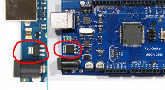
I don't have an actual photo but looking at the Mega in this photo, notice the power pin section on the board at the bottom directly to the right of the factory 7 to 12v power input, I connected directly to those pins, the 5v and gnd there are 2 gnd pins there and either can be used for the ground wire and you no longer need the 7 to 12v wall wart, the 5v 6a supply will power the Mega, the screen ,and pretty much anything else you'll ever connect to the board