redtop's Ferduino controller

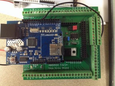
got a lot of my screw shield assembled today, I don't have the screw terminals or the RTC battery clip in yet, still waiting on those, but the RTC works perfectly on it, I've not tested the power supply connected to it yet either

this thing is gonna make bench testing different things so much easier to do, I love it
 
there was a guy who made them for the original jarduino people but they where for the small screen and he would ship them from Ireland so you might do better from a local shop.
 
there was a guy who made them for the original jarduino people but they where for the small screen and he would ship them from Ireland so you might do better from a local shop.

yep, compfranon from the Jarduino web forum was making the bezels for the 3.2s screens, I was gonna get one from him but I no longer need one that small :D

I'm gonna try it using wood, if I can't make it look to satisfy myself, I'll try other options, I really would rather make it from red oak to match my other home furnishings but we'll see how that goes :D
 
got my battery clip in and soldered up on the screw shield and battery installed, clock works perfectly and keeps it's time when disconnected from the USB so all is well there, now all I like are the screw terminals and it'll be complete :D
 
Willie you getting around to meet everyone aren't you if you ask him he might just make you one the dimensions of the screen shouldn't be to hard to find on line or just measure it your self using metric and your all set.

Soldering in the terminal pins is fast and easy I found it makes them look better if you connect them all together first on the sides they are tung and grove don't know if you knew that or not. but put all in tape them down and solder all in a row
 
Willie you getting around to meet everyone aren't you if you ask him he might just make you one the dimensions of the screen shouldn't be to hard to find on line or just measure it your self using metric and your all set.

I may do that, I thought that you being in Ohio and knowing an acrylic shop locally, it might be less expensive to get them to make it, I don't know anybody local here that messes with acrylic

Soldering in the terminal pins is fast and easy I found it makes them look better if you connect them all together first on the sides they are tung and grove don't know if you knew that or not. but put all in tape them down and solder all in a row

yep, I've soldered the screw terminals in before :D but then, I've soldered the stackable headers in also and ended up having to redo a couple of those LOL thanks for the suggestions
 
this what I am using for my enclosure and will have a lot of room for every thing inside and it is water tight

I did not make the extra piece to go on the Ethernet shield I just added some extra double high pins that I had. seemed to work great so far

I added them on the 7 and 8 is one pair and hen 9 threw14 is another then the double row header he on the other side by where the 2 red jumpers are
 

Attachments

  • mini-IMG_0975.jpg
    mini-IMG_0975.jpg
    82.7 KB · Views: 31
  • mini-IMG_0985.jpg
    mini-IMG_0985.jpg
    59.5 KB · Views: 31
  • mini-IMG_0990.jpg
    mini-IMG_0990.jpg
    60.5 KB · Views: 32
I was thinking the same thing

I do have a question about all the diffrent things being hooked up to the arduino can every thing just get wired directly to the arduino pins and is that safe
 
hi all
rott can you tell me what post has the ph circuit board bom i am getting ready to head to the elec parts store and would like to get parts for it too
 
I will be using ph stamp from atlas go back to page 1 of this thread and read it is half way down I think I don't believe there was a DIY one
 
I was thinking the same thing

I do have a question about all the diffrent things being hooked up to the arduino can every thing just get wired directly to the arduino pins and is that safe

a lot of the stuff I had wired up on my Jarduino was soldered directly to the pins, you just have to be careful and not cross the pins with the solder, they are close
 
marspeed sent me one maybe it was from another thread it uses the atlas stamps i just wanted to know what the rest of the components were he sent me the bnc plugs the caps and ic that goes on it along with the headers for the stamps to plug into
 
I am sorry I thought you where talking about making a home made circuit I have the same one from marspeed but sounds like you have it all
 
what i need to know is what goes in position 1-8 is that a DB -9 fitting?
and what connects to a-d it looks like a is grd and d is+voltage ?
what is c and b for is this hooked to an I2c port? i have looked all thru this thread and could not find anything about it unless i missed those posts
 
on another note got all the parts for the screw shield except the screw terminals and the cr1220 battery where did you guys get the terminals from my local electronics supply didnt even have anything close to fitting them. it is all soldered up and working had one little glitch that had me scratching my head and cussing but finally figured it out i had soldered the jumper wire that goes on the underside of the board to the wrong pin mars even had it marked my eyes are not what they used to be LOL
 
A-D are a single row of pins and I didn't put the 8 pin connection on yet but I remember him talking about it being Ethernet but then that's 4 twisted pair
I think that is it
 
hi all

hey rott after what you explained i was wondering what he had ethernet hooked up to the stamp board then it dawned on me thats how it is powered and signals are sent back to the arduino do you have the ethernet jack if not send me your address in a PM i have some left over from another build

i now have the screw shield done except for the screw terminals
and the Ph board is done

now to get the programming done and working
 
Back
Top