My first post and first saltwater tank - have been doing planted tanks for several years and decide to take the plunge into more advanced chemistry:lmao:. To save money I am using a 25 gallon tank I already have and adding to it an eshopps overflow. Also I'll be converting my 9 gallon Fluval Flex into a sump. I intend to set it up as a refuge style sump since the lid has a nice built in light that'd be good with macro Algea.
I'd like your help with converting the Flex 9 into a sump. As an overview, fluvial flex has a sump area, in the back, for filtering the water and returning it back to the front. A black acrylic panel separates the back from the front.
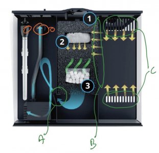
The first attachment shows the back portion with the typical water flow - enters the tank at the grills I marked as C, flows into a foam block through grills marked B and then to the return chamber through an opening marked as A.
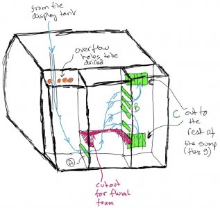
Unfortunately, the rear area is not deep enough to accommodate a proper return pump (only about 2" deep. So instead, I plan to use it as the input area to the sump. So as shown in the second attachment, I'll have the water from the 25G display tank go into what used to be the return chamber. Then it'll flow through the foam block to remove coarse debris. Finally it'll flow into the last chamber (what used to be the input chamber) which will contain floss to remove the fine debris. From there it'll move to the front (main) part of the flex 9 which will contain the return pump to the 25G DT. Essentially the flow path will be the exact opposite of what it was originally.
I'd love to get your input on this design and if you notice any flaws, or can suggest improvements please let me know. I've never used a separate sump tank before so any input you may have would be very welcome.


