Sump Virgin- Please help designing plumbing/sump/return

BigJohnny

Active member
Hey Reefers,

I've been a sumpless reefer for 2 years now (not my choice but due to gallon restrictions imposed by landlord). Just bought a house and will be starting a new 90g DT/40g Sump build.

I have never built a sump before but have a general idea of what id like, I am just not sure how I should place the baffles to minimize issues/maximize performance.

I will be converting a 90g rr to Herbie with HOB return (or drilled if i feel brave and the back isnt tempered). The 3/4" will be full siphon and the 1" drain will be emergency (haven't decided on 100% dry or trickle yet). Then there will be a 3/4" return.

I plan on building my stand 40" tall because I am 6'4"with long arms, hate crouching all the way down to view my tank, and have determined that it is the ideal size for viewing while still maintaining ease of maintenance. I also like the idea of having all that vertical room under the stand.

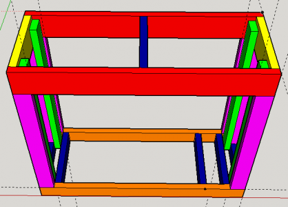
Here is a sketchup of my stand. Basic 2x4 construction (based on Rocket Engineer's plans) except i am using 2x6" for the top frame just in case. The stand is tall enough that it doesn't mess with my under stand space so why not. The additional supports on the bottom are to support the 40b sump completely around the trim. I will be skinning it with 1/2" or 3/4" ply and the sump will sit on ply as well.

Let's start with Stand:

What dimensions should i actually build the top and bottom frames? Deep Blue 90g RR Corner overflow dimensions are supposedly 48"x18"x24", but i know that is not exact and it is better to have a little underhang than any overhang. Currently its 49x19 in sketchup

Return pump/Plumbing:

-What size return pump would I need? Im thinking the sicce syncra 4.0 (about 950gph) but i dont know if that is a good match for the setup/drain and return size/stand height/tank height.

-What type of plumping?
==>Schedule 40 or Schedule 80?
==>Besides gate valve to tune full siphon, what additional check valves/unions should i get and where should i place them? I want safest set up possible.
==>I am told the emergency going straight down is best (and the full siphon too i guess), but due to the corner overflow and sump location i will need either some 45 degree or flexible tubing for one if not both drains, which is better?
==>flexible tubing or hard plumbed return?

Sump
I think i want 3 sections from left to right, drain1 filter sock)/skimmer section (vertex omega 150), refugium, return section.
i believe a forced under baffle than over another baffle from the drain/skimmer to the refugium is a good bubble trap(so im told).

My biggest concern really is, how do i control which section evaporates/to use the ato on, and how tall do i make the baffles to keep everything at the proper level for equipment function. I also dont know how much i have to adjust that based on return pump shutting off and the sump being able to accept the additional water volume. I was planning on only using about half the water volume of the sump which im told leaves plenty of spare room. The refugium is my lowest priority so i would rather improve all other aspects and shrink the refugium if necessary.

I have a tunze osmolator which is an epic ATO in case that matters. ATO container will be outside of the stand.


I cannot tell you how much i would appreciate some of you experienced reefers walking me through this. Especially if someone has a similar set up or even just a 40b sump, pictures and assistance would be greatly appreciated. I'm a little nervous about the whole thing so you guys would really be doing me a solid.

Thanks so much!

-Big J
 

Attachments

  • 90g stand.PNG
    90g stand.PNG
    19.8 KB · Views: 0
The sections communicate and will equalize. Put the ato sensor into the largest, the hose from the ato pump into some place you can make it absolutely secure: having it flip out and flood the area as the ato sensor continues to read "need more" is not a fun day.

The third chamber, the pump chamber, needs to be protected against the snails and moss you may have growing in the middle chamber. So a fairly tight over-under pair of walls, leaving just enough room for the heater, will let you insert a piece of some barrier material to protect the pump(s) [probably also your skimmer pump] in the third chamber. Your middle chamber may need to house or support the skimmer itself, depending on style (in-tank or hang-on) and size (some are huge.)
 
The sections communicate and will equalizeYou mean they will all lose water equally? I swear ive read some people say only one section goes down, for example the return section or something. Put the ato sensor into the largest ok great, the hose from the ato pump into some place you can make it absolutely secure: having it flip out and flood the area as the ato sensor continues to read "need more" is not a fun dayi bet haha.

The third chamber, the pump chamber, needs to be protected against the snails and moss you may have growing in the middle chamber. So a fairly tight over-under pair of walls, leaving just enough room for the heater, will let you insert a piece of some barrier material to protect the pump(s) [probably also your skimmer pump] in the third chamber. Your middle chamber may need to house or support the skimmer itself, depending on style (in-tank or hang-on) and size (some are huge.)makes sense, do you think i shouldnt put my skimmer in the first section and rather with the return? it is a vertex omega 150 internal skimmer, foot print 9"x12". ideal water depth 7-9.5". in most designs ive seen it with the drain/first section (for example with ruby/trigger sumps and several DIYs).

thanks so much for your input! Any thoughts on the plumbing/return pump aspects? I've seen you post all over the forum many times throughout my research, and i respect your opinion and know you have a lot of experience.
 
Here's a really good primer on sumps, and elswhere on that site he has diff designs that will give you an idea of your options. http://www.melevsreef.com/node/710

The water level is lowest in the section where the return draws from. The water will equalize on either side of a baffle where it can, but it won't like leap over a baffle to the other side to do it. So if the return pump is separated from the rest of the sump by a baffle that goes all the way to the floor, the water level is even until it gets below the top of that baffle, and then lower on the pump side. The link above has a little animation that shows that effect, it's obvi when you see it in a picture.

If you let that "over" baffle determine your water height - which is good for skimmers, then you want your ato sensor in the return pump section.
Thanks, this is great!

Sent from my SM-G900V using Tapatalk
 
Last edited:
So many different opinions here, anyone with a lot of experience have a preferred way to determine return pump gph?

Sent from my SM-G900V using Tapatalk
 
I'm planning the same build in March. I'm doing a B Animal overflow. Your back isn't tempered. That is usually on older tanks that you find on craigs list. Go in to drilling with confidence and research it's not hard. Your return section with the pump in it will be the only section where evaporation is noticed. Every other section is topped of by physics. Put your ATO into the return section. Measure from there always.
 
So many different opinions here, anyone with a lot of experience have a preferred way to determine return pump gph?

Sent from my SM-G900V using Tapatalk

the way I select a return pump is based on the following:

(Display tank volume - estimated displacement x 5) - estimated plumbing head loss + additional ancillary equipment needs = return pump size.


This means that you would take your total volume of 90 gallons and subtract some from that since the rock and sand will displace some. Since I have no idea how much rock and sand you will put in it, let's just say arbitrarily that you'll have 5 gallons of displacement. So your total display volume would be about 85g. Multiple that by 5 since you want about 5x turnover. So to turnover just the tank at this point you will need 425 gallons.

Now you need to calculate your return plumbing head loss. You can use this:
http://www.reefcentral.com/index.php/head-loss-calculator

That calculator will make sure the pump you select will be able to meet your needs taking the plumbing into account.

After you have the pump selected, go up a size. You can always dial it back if it's too much, but if you need more volume for ancillary equipment like reactors, etc, you'll have to spend more money on another pump.
 
I'm planning the same build in March. I'm doing a B Animal overflow. Your back isn't tempered. That is usually on older tanks that you find on craigs list. Go in to drilling with confidence and research it's not hard. Your return section with the pump in it will be the only section where evaporation is noticed. Every other section is topped of by physics. Put your ATO into the return section. Measure from there always.
Thank you, good luck with your build!

Sent from my SM-G900V using Tapatalk
 
the way I select a return pump is based on the following:

(Display tank volume - estimated displacement x 5) - estimated plumbing head loss + additional ancillary equipment needs = return pump size.


This means that you would take your total volume of 90 gallons and subtract some from that since the rock and sand will displace some. Since I have no idea how much rock and sand you will put in it, let's just say arbitrarily that you'll have 5 gallons of displacement. So your total display volume would be about 85g. Multiple that by 5 since you want about 5x turnover. So to turnover just the tank at this point you will need 425 gallons.

Now you need to calculate your return plumbing head loss. You can use this:
http://www.reefcentral.com/index.php/head-loss-calculator

That calculator will make sure the pump you select will be able to meet your needs taking the plumbing into account.

After you have the pump selected, go up a size. You can always dial it back if it's too much, but if you need more volume for ancillary equipment like reactors, etc, you'll have to spend more money on another pump.
Thank you very much this was very helpful and exactly what I'm looking for. The only thing this doesn't take into account however is the herbie full siphon drain. I am told that since I am using the 3/4" hole as the full siphon, I may be limited in terms of a return pump. This apparently is due to 2 reasons:

1. I need to make sure that my return pump doesn't push more than the 3/4" can handle before the full siphon engages

2. That will be restricted even a little more because I actually have to use the gate valve a bit to tune everything initially.

What is your opinion on that?

Sent from my SM-G900V using Tapatalk

My opinion is that you need to drill a bigger hole.

3/4" at full siphon will only drain about 250-275gph. You need about 2x that amount.

Why are you only doing 3/4"?

Here's bean animals table on pipe volumes
bulkhead_flow_rates.jpg
 
My opinion is that you need to drill a bigger hole.

3/4" at full siphon will only drain about 250-275gph. You need about 2x that amount.

Why are you only doing 3/4"?

Here's bean animals table on pipe volumes
bulkhead_flow_rates.jpg

Are you sure the 3/4" isnt 250-275 is before full siphon...? I'm converting a reef ready to herbie. It has 1" and 3/4", other people who do that use the 1" for the emergency. Also I'm pretty sure the distance dropped effects full siphon flow doesn't it?

Sent from my SM-G900V using Tapatalk
 
Are you sure the 3/4" isnt 250-275 is before full siphon...? I'm converting a reef ready to herbie. It has 1" and 3/4", other people who do that use the 1" for the emergency. Also I'm pretty sure the distance dropped effects full siphon flow doesn't it?

Sent from my SM-G900V using Tapatalk

The table is for full siphon at different drop distances. The numbers at the top are the inches of drop for the siphon line. You'll see the gph estimates for each size go up as the drop increases. So 12" of drop with a single 3/4" sch40 drain will handle 771gph. Just extrapolate the chart for your specific application; I.e 24" of drop would be 771x2, so forth and so on. I'm not sure what I was drinking when I said it would only flow 250-275gph.
 
Last edited:
@Bent, is there a different calculator that just gives a head-feet equivalent calculation due to friction and fittings and horizontal/vertical run, one that is pump-agnostic? I could then look at any pump's performance curve and see the gph. The standard RC one you reference has a pretty restricted (older) pre-defined set of pumps.
 
@Bent, is there a different calculator that just gives a head-feet equivalent calculation due to friction and fittings and horizontal/vertical run, one that is pump-agnostic? I could then look at any pump's performance curve and see the gph. The standard RC one you reference has a pretty restricted (older) pre-defined set of pumps.

I've always just took the GPH from a pump I was thinking about getting, looked up a random pump in that list, and tried to find one that had similar output.
 
I've always just took the GPH from a pump I was thinking about getting, looked up a random pump in that list, and tried to find one that had similar output.

Problem is that different pumps with the same or similar GPH have different max head values, meaning I'd think different performance as you followed that curve up in head value.

Would it work to take the output from one of the friction head loss calculators, e.g. http://www.freecalc.com/fricfram.htm, which account for everything EXCEPT vertical rise (weird) and then add that to your known vertical rise to yield a decent head loss estimate? You can then take that and look at any pump's performance curve to see your expected GPH for that situation.
 
Back
Top