ReefkeeperZ
New member
Pretty cool thread can wait to see what else comes out of it
Pretty cool thread can wait to see what else comes out of it

Doesn't the edit option only remain available for a short time after then post was made?I asked the same thing in another thread, it's based on post count (over 50) and duration I believe they said it's 90 days
Just waiting on the controller/driver board from a certain someone
Doesn't the edit option only remain available for a short time after then post was made?
Tim
High level turn off the output
Low level Open the output
Just waiting on the controller/driver board from a certain someone
nice i'm watching that thread i hope he gets his light going. its a nice controller neater wiring than my setup.

Hey, I'm in no real hurry :wave:
I'd rather it be easy to do right so I get my two perfect boards.
Still haven't had the time to fool with code yet.
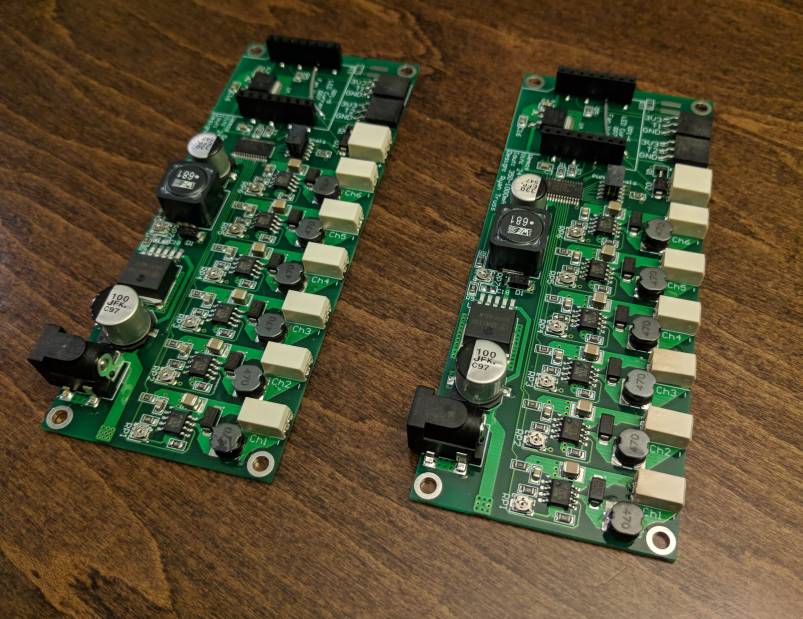
Hate waiting for parts to arrive... Threw together a design for an 8 channel driver since I can't build anything yet

Does it make sense to use a barrel connector with a header for PWM? Better to just use wire to board connectors for input voltage as well perhaps?
For power, barrel jacks work if used in ratings, but I would want something like a screw terminal strip or Molex headers up at High currents.
The safe limit for #18 wire is about 12.5 A, then #16 is 15 A. The actual Molex connector itself is the weak point though.
I made up a testing bench for HID headlights and two 35 W ballasts pull about 6 A each form the 12 V rail on start-up then fo down to about 3.1 A each. After a couple months of on off cycles, the Molex connector turned from a semi opaque white to having brown burn marks all around it. So I would definitely stick to 11 A (132 W) on the 12 V side as the maximum current being pulled from a single cable coming out of the PSU.
I personally like to use 1/8" stereo headphone style jacks for PWM, but a header would work too. Could always do up a quick harness to plug into it that runs to the endcaps of the fixture, also more versatile for running things like cat6 RJ45 sockets for PWM.
For power, barrel jacks work if used in ratings, but I would want something like a screw terminal strip or Molex headers up at High currents.
The barrel jack used on the Wemos board is only rated for 6A I think so I'll probably change it to something like the PTSM series (same connectors used on the blue acro driver) with two pins for positive and negative. RJ45 would be nice but it's only 8 wires so you don't have enough. I'll probably just leave it as a header for signals so people can use what they want, no point trying to limit it since it's not an all-in-one type board anyway.
")