trying to hack 10V control into Evergrow D120

Eud

New member
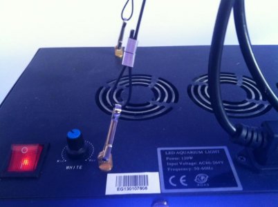
I took out the little board that the dimmer pot sits on in a D120 LED, and I'm trying to figure out what it does. I let the smoke out of one testing stuff with a battery and blew the little transistor (base shorted to emitter now) so it doesn't work anymore, but I have one left and am being careful with it.

Here is what I've figured out so far.

a830451de208145e2f51d721fc8cad4d_zps50de6e2a.jpg


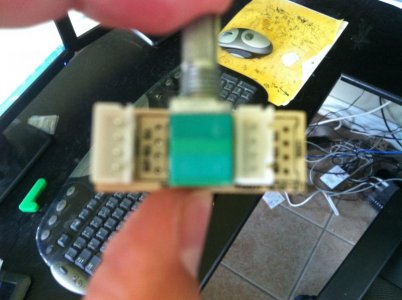
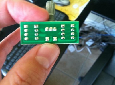
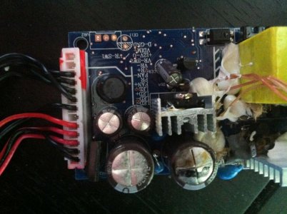
Can someone smarter than me tell me what is going on in this circuit? There are no numbers on the capacitor or the transistor. Our electrical engineer at work kind of scratched his head and couldn't figure out if the thing was trying to supply a dimming current to the driver or a voltage or both or what.

My first idea was just to desolder the pot and put in a digital pot which I could control from an Arduino, but it's a 500k pot, and they only seem to come up to 100k.

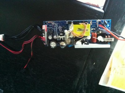
Second idea was to take the entire board out and put 0-10V across the output pins since it only draws 2.34mA at max dim with 0.649V measured at the output pins and 0.02mA at full bright with 9.87V measured at the output pins, so I'd just use an Apex to supply those voltages, but I think that's naive to do without knowing what the board really does.

Any help from circuit heads?
 
In case anyone is interested, that complicated board in a D120 that the pot is mounted on is to linearize the dimming operation and get you a full range of brightness on the LED string by getting the taper right across the potentiometer. Plus it has a little bit of hardware to make it not noisy when you're turning it.

I'm going to replace the whole thing with a 25k digital potentiometer and control that with an Arduino Uno.

Here's a plot of resistance on the pot across the two dimming wires in a D120 vs current on the LED string. Max current is at 20k Ohm.

D120Resistance_Vs_LED_String_Current.png

I may put in a tapering resistor on the output of the digital pot to give a bit more resolution at low resistance since the slope is so much higher down there.
 
I got it working. It turned out to be really simple. Just put the Apex VarSpd port on the Dim+ and Dim- pins of the d120 board and short out the other two pins on the little daughter board. No need for a digital pot at all.

Video below.

http://youtu.be/-qAyKw9vfW4

You could use an op-amp configured for unity gain to isolate the d120 from the Apex, but it doesn't seem to hurt anything at least for the 20 minutes or so I was running it. Not sure if the VarSpd ports will like it long term, but the max current I observed going through them was 2.33mA, at minimum brightness, so it seems like it will be fine. At max brightness it was only drawing 20 microAmps.
 
eud, this stuff seems all above my head, but i'd love to get the value series to work on an apex, could you post a simplified explanation with pictures perhaps? Thanks. If it's easy to replicate what you just did, this could change everything.
 
found your wamas thread, holy crap you guys know your stuff. i registered just so i could see the pictures. my head is in a complete loop now.
 
Did you really need to post this?! I haven't even gotten mine in the mail yet and now you have me thinking about tearing it apart! :lolspin:
 
I am trying to isolate the apex from the d120 using a unity gain op amp with instructions from Tom at WAMAS. Will know this weekend if that helps me dim to zero and also gives some protection for the apex.
 
It wouldn't damage the apex in reality would it? Only the vdm channel correct, in assuming that you have the full apex? Hats off to you for doing this, I always said I was going to try but never had the cajones.
 
Probably not, but I asked over on the Neptune Systems forum if it was ok to source 2.5mA of current into the VDM ports, and RussM there said that no current should ever go back in. I dont blame them for not wanting to say it's ok. Will be nice to dim all the way down anyway of the opamp thing works. Also, yes, I used the ports on the vdm, not the main unit.
 
Did they switch up the circuitry on the dimmer? I had to replace a blown driver on one of my lights and when I opened it up my dimming boards appear to be just the analog dimmer itself. For what it's worth I know virtually nothing about electrical engineering.

I attached some pictures (along with one of the lights since technically I didn't buy direct from Evergrow, but I'm pretty sure it's just a rebranded D120).
 

Attachments

  • photo (9).jpg
    photo (9).jpg
    42.7 KB · Views: 3
  • photo (8).jpg
    photo (8).jpg
    56.6 KB · Views: 4
  • photo (7).jpg
    photo (7).jpg
    46.9 KB · Views: 3
Couple more pics of the blown driver's board. To me (again I'm a layman) it looks like they may have moved some of those functions into the board on the driver.....
 

Attachments

  • photo (10).jpg
    photo (10).jpg
    59.6 KB · Views: 4
  • photo (11).jpg
    photo (11).jpg
    70.5 KB · Views: 3
Next question, can you connect 3 lights together per channel? My controller has 2 variable voltage ports up to 10v for white and blue.
 
Couple more pics of the blown driver's board. To me (again I'm a layman) it looks like they may have moved some of those functions into the board on the driver.....

You're right. It does look like it's just the pot on your small dimmer board and they might have done the other stuff inside the driver. In our club we seem to be able to order extra drivers from the company pretty cheap. If you're handy enough to take it apart you could probably install a new one. I don't know the details of ordering them because I don't do those group buys, but I could find out if you need.

Next question, can you connect 3 lights together per channel? My controller has 2 variable voltage ports up to 10v for white and blue.

I kind of doubt that you can just put multiple lights per channel, but I'm not an electrical engineer. I do know that the way they dim is by sensing current across a resistor internal to the driver. Seems like multiple drivers linked together across this 10V signal from the Apex would affect each others' readings.

There is probably some way to connect multiple lights together using one op amp per channel where you send the 10V signal using the Apex to the input side of three different op amps and then send a separate output to each Apex. I never really got the op amp to work that I was playing with since I ended up spending time getting my tank build wet and now am fiddling with stuff on it. I'll revisit it at some point.
 
the-republican-party-isn-t-conservative-enough.html
Couple more pics of the blown driver's board. To me (again I'm a layman) it looks like they may have moved some of those functions into the board on the driver.....
attachment.php

Ahhh.. looks like the ole "capacitor rot" (second big one to the right)so common. soooo annoying..
10 cent parts.. making millions of electronic parts useless..
 
Last edited:
the-republican-party-isn-t-conservative-enough.html

attachment.php

Ahhh.. looks like the ole "capacitor rot" (second big one to the right)so common. soooo annoying..
10 cent parts.. making millions of electronic parts useless..

I have rebuilt I bet 20 power supplys for LCD monitors due to blown capacitors. Pretty easy to do.
 
Back
Top