Apex I/O Box

tuckdawaytoo

New member
For those of you with an apex that would like a quick I/O alternative:

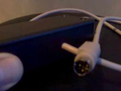
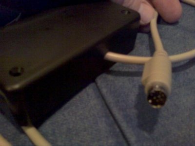
I purchased a six foot 8 Din Male to Male connector here for $8:

http://cgi.ebay.com/MD8-Mini-Din-8-M...item5635a0a7fb

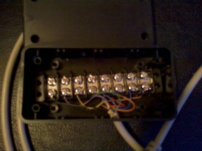
Went to Radio shack for 8 section terminal block $2.99

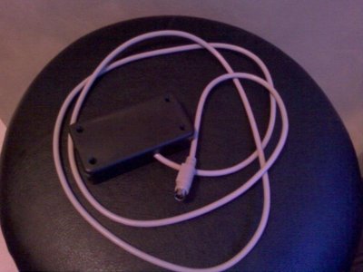
and Project box $2.99

Total $14

I cut the one end off the connector checked each wire and matched color to pin # using meter:

Pin 1 BRN
2 BLU
3 ORG
4 RED
5 GRN
6 YEL
7 PRP
8 BLK

Works great. If someone wants a photo let me know.

The terminal bar is great as it has two sides with screws you attach the side from the Apex to one side of the bar and then the other side has 8 screws to attach each of your items.
 
Ha! That is exactly what I did, right down to the Radio Shack terminal block and ebay source for the cable. I bought a project box ended up not using it; just screwed the block to the inside of my stand. I also bought a separate block for the ground so I wouldn't have to put all of the switch grounds on the same terminal.
 
Great idea on the ground so you do not have to end up unscrewing the original ground wires each time....off to Radidio Shack...again.
 
Apex I/O

Apex I/O

Here are the photos you will see the terminal bar with 8 double sided positions in the 2nd photo.

Added the last photo so you can see I drilled only a large enough hole for the Mini-din cable on one side and the same size hole on the other.

I might add some loom to the bunch of cables from my switches for protection.
 

Attachments

  • PIC_0311.jpg
    PIC_0311.jpg
    45.2 KB · Views: 0
  • PIC_0312.jpg
    PIC_0312.jpg
    44.8 KB · Views: 0
  • PIC_0313.jpg
    PIC_0313.jpg
    29.5 KB · Views: 0
  • PIC_0314.jpg
    PIC_0314.jpg
    34.2 KB · Views: 0
Check me on the wire color / location. Just installed two switches to ATO and I had a couple reversed. It appears that I was touching the casing of the I/O cable..heard the audible humm and moved on to the next...duh.

Very simple to verify just use your power meter and check for continuity between the pin location and end of wire.
 
I copied Kenargo's design and used 3.5 millimeter jacks. I put 10 jacks in because I wanted to have the option to have more than one input in parallel.
4139634623_9be8f396ea.jpg
 
I am making a similar box, only a little different.
I am using 2x 8 terminal blocks. 1 for all the power connections and the second one for all the grounds.
1 on each side of the box.

I figure it will make hooking the wires up easier as you do not have to stuff all the ground connections into one terminal.

I have a question. Can a LED be placed in the I/O box to show the status of each switch just by looking at the I/O box?

Does anyone know how if the voltage and amperage of each switch line on the Apex is is enough to run a LED?

What I would like to do is insert 6 LEDs into my I/O box so that a LED will change its light status for each completed / broken circuit.
 
Last edited:
I have a question. Can a LED be placed in the I/O box to show the status of each switch just by looking at the I/O box?

Does anyone know how if the voltage and amperage of each switch line on the Apex is is enough to run a LED?
The voltage on the switch inputs is intended for signaling only... there is not enough 'juice' to power anything.
 
yeah you would need an external power source to drive the leds. however, you can create dummy outlets that will show you the status of the switches via the apex
 
In reference to the color code posted above. I bought a mini din cable which had all the same colors but the pin#/color call outs were waaay different. Mak sure you verify which color goes to which pin.
 
Anyone know where to get this din cable. Maybe a radioshck or best buy. What is the cable for? Is it for computers? Thanks
 
No luck finding that cable at Rad shack, I tried today.

Also you guys should try using the panel mount rca connectors only 2 contact points so none are wasted and they are cheap to buy.
 
Back
Top