You are using an out of date browser. It may not display this or other websites correctly.
You should upgrade or use an alternative browser.
You should upgrade or use an alternative browser.
basic LED help
- Thread starter salty joe
- Start date
salty joe
Active member
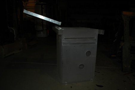
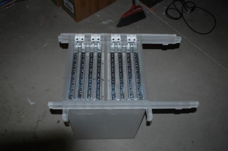
First pic water enters through two holes and exits the slot across the top of all four sides after flowing through the algae.
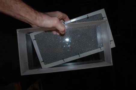
Another view with epoxy coated washer on bottom for pulsing power head to agitate algae, if needed.
Boat and screen.
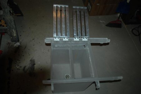
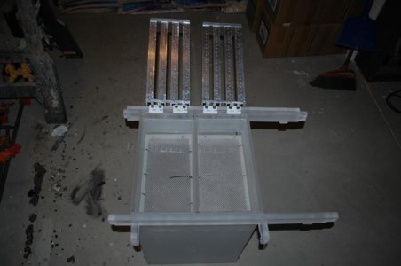
Boats and screens installed.
Running position.
This thing sets inside the filter.
Another view with epoxy coated washer on bottom for pulsing power head to agitate algae, if needed.
Boat and screen.
Boats and screens installed.
Running position.
This thing sets inside the filter.
Attachments
Nice.
Couple questions/observations.
Is there something between the leds and water to keep them from being splashed? or getting condensation/salt spray on them?
It looks like you have a clear cover over the back of the heatsinks? this will prevent them from cooling and they will burn up without a fan forcing air into the unit. (especially if you are using "ebay special" button type leds (anything other than cree or luxeon).
With the LEDs spaced that close on the channel (assuming 1" channel as you said and not the more common inch and a quarter) you will not be able to drive the LEDs much over 350mA without a fan for cooling or they will over heat and burn, plus you won't be able to touch the heatsink without possibly getting burned. However if you have a fan to blow even a small amount of air over the heatsinks I'd have no reservation running them up to 500mA. (700mA is really streaching it for those type LEDs) As close as they are to the screens I don't think you'll need more than 100mA to produce sufficient PAR for a good mat of algea.
What are you doing with all the space below the screen? Seems like lots of wasted space that could be used for growing algea if the screens were vertical?
salty joe
Active member
Nice.
Couple questions/observations.
Is there something between the leds and water to keep them from being splashed? or getting condensation/salt spray on them??
The bottom of the 'boat'. The LEDs and heatsinks swing inside the boat. The sides of the boat extend to the top of the unit. I guess we'll have to see how much trouble salt creep is. There's no splashing or crazy turbulence.
It looks like you have a clear cover over the back of the heatsinks? this will prevent them from cooling and they will burn up without a fan forcing air into the unit. (especially if you are using "ebay special" button type leds (anything other than cree or luxeon).?
With the LEDs spaced that close on the channel (assuming 1" channel as you said and not the more common inch and a quarter) you will not be able to drive the LEDs much over 350mA without a fan for cooling or they will over heat and burn, plus you won't be able to touch the heatsink without possibly getting burned. However if you have a fan to blow even a small amount of air over the heatsinks I'd have no reservation running them up to 500mA. (700mA is really streaching it for those type LEDs) As close as they are to the screens I don't think you'll need more than 100mA to produce sufficient PAR for a good mat of algea.
There's no cover on the heatsinks. Bad pic.
I was gonna ask you guys about a fan...on the other hand even the ebay LEDs I got should produce less heat per watt than a CFL. So each length of heatsink with 10 3W LEDs would need to handle the heat produced by a 27W, the so called '100W', CFL. And yeah they get plenty warm, but I don't think hot enough to burn me. And each heatsink has a lot more surface area than a CFL to lose heat. Don't get me wrong-I'm not saying I know this is how it will be-because I don't. Just my gut feeling. I will definitely take it slow and careful. I guess I better start thinking about fans.
As for PAR, again IDK how much will be needed to push the algae to photo inhibition, but it will likely be intense. I'm looking for this scrubber to grow a lot of algae in a hurry. We'll see. I appreciate your advice and help. Thanks a ton.
What are you doing with all the space below the screen? Seems like lots of wasted space that could be used for growing algea if the screens were vertical?[/QUOTE]
It's underwater-would be tough to light vertical screens. I have not enough room above for vertical screens. It's a refugium by default.

Last edited:
Ok, couldn't tell from the pics. I don't think salt creep will be much of an issue. I was mostly concerned that it looked like there was a cover over the heatsink in the one pic, guess it was just a trick of the camera.
I mention heat as I've built numerous arrays in that fashion on 1" C channel. Running at around 400mA with a spacing of ~3.2" between LEDs the heatsinks will reach around 105 degrees Fahrenheit. Much warmer than that and you might not get burned per say but you won't wan't to touch the heatsink, and more to the point the LEDs will be running too hot internally and they will burn up over time. Not right away but over a few months the light output will begin to drop considerably and the diodes and packaging around them may begin to blacken and burn. The button type LEDs have poor thermal transfer from the internal junction thru the star chip and onto the heatsink. So the junction of the LED (the temperature that really matters) will be running several times hotter than the heatsink, more than double in most cases.
Current under 300mA and you shouldn't need fans but much more than that and you will for sure.
At 2-3" and ~400mA you can expect to see between 200-300 PAR without lenses (measured on one of my Arrays with an Apogee meter), maybe more with the close spacing you have and if you have more efficient LEDs than the ones I measured which have been running for a couple years now. PAR drops off very rapidly the farther you get away from the diodes, just like with fluorescent bulbs.
With lenses (60 degree) you would see 600-800 or more PAR from the same diode at that distance and it will remain more intense further away since the light is focused and not going out in all directions. I would consider adding lenses since that is where the efficiency is gained with LED lighting, the ability to focus the light and since color blending/disco effect (aesthetics) isn't an issue on a scrubber you can use far less power to achieve the same algea growth.
salty joe
Active member
The LEDs getting way hotter than the heatsink makes sense, especially after taking a close look at them. They do look like buttons, must be what I have. I wonder if a tiny bit of thermal grease at the button/star junction would help.
It shouldn't be too much to get fans in position. Does a pair of 60mm fans centered perpendicular over each scrubber sound good? The fans I was looking at are 12V. Would they need a separate power supply? Could the magic of the arduino use the same timer for the fans as the lights?
I'll have to re-think lenses. I was thinking that since the LEDs are so close, the best thing would be no lenses....One good thing is the light is close to 100% PAR. Should be anyway.
How fast are LEDs advancing? Is what was best last year what gets sold on eBay for cheap?
salty joe
Active member
I found some 5V fans I think would do the trick. They have a 2 pin connection, is that what I want? Some fans have 3 pin connection. Is it possible to connect the fans to the same dimmer that controls the LEDs? If that adds much complexity, I'll run the fans wide open all the time. I have another 5v wall wart with plenty of amps.
I diagrammed what 60 degree lenses would do with this setup and was quite surprised at the nice overlap. I would not have considered lenses, great suggestion-they are on the way.
Thanks guys!
I diagrammed what 60 degree lenses would do with this setup and was quite surprised at the nice overlap. I would not have considered lenses, great suggestion-they are on the way.
Thanks guys!
Gorgok
New member
A 3 pin fan is usually still just a simple DC motor and can be powered without the 3rd wire (which is usually a rpm sensor). Fans vary greatly in amperage, ones i use use something like 80mA on a 120mm fan, while others i have had use as much as 500mA. They should say what they use on the sticker over the shaft on the fan frame.
In the order of your questions.The LEDs getting way hotter than the heatsink makes sense, especially after taking a close look at them. They do look like buttons, must be what I have. I wonder if a tiny bit of thermal grease at the button/star junction would help.
It shouldn't be too much to get fans in position. Does a pair of 60mm fans centered perpendicular over each scrubber sound good? The fans I was looking at are 12V. Would they need a separate power supply? Could the magic of the arduino use the same timer for the fans as the lights?
I'll have to re-think lenses. I was thinking that since the LEDs are so close, the best thing would be no lenses....One good thing is the light is close to 100% PAR. Should be anyway.
How fast are LEDs advancing? Is what was best last year what gets sold on eBay for cheap?
They should and almost always do already have thermal compound beneath the button, but most of the ones sold on ebay are hand solderd (round blob of solder is a dead givaway) so thermal junctions and tolerance is not good.
I'd go with larger fans 92 or 120mm fans they are much quieter. 12v fans are cheap and running them off of about 6 or 8volts to make them quieter should be plenty of air, if not even a bit excessive. (60mm fans are crazy loud FYI compared to larger formats that move the same amount of air) and only useful if space is truly limited, IMHO.
Lenses will cut your power use in half at least (relative to the PAR level per watt actually delivered to your scrubber screens) Well worth it in my opinion with those type LEDs since you can run them at lower power thus keeping them cooler. Just my two cents though.
Rapid LED and Steve's LED for the currently best and affordable hobby leds. Ebay sells crap from a decade ago still. button style were phased out from most all comercial lighting over 6yrs ago (Cree xre being the exception, but they still are not cheap). The cheap Semi type ones Steves is selling for under $2 are easily twice or three times more powerfull at the same drive current compared to what you got from ebay. (don't fret though what you bought will be more than enough for your scrubber and should last you years)
button type led:

I found some 5V fans I think would do the trick. They have a 2 pin connection, is that what I want? Some fans have 3 pin connection. Is it possible to connect the fans to the same dimmer that controls the LEDs? If that adds much complexity, I'll run the fans wide open all the time. I have another 5v wall wart with plenty of amps.
I diagrammed what 60 degree lenses would do with this setup and was quite surprised at the nice overlap. I would not have considered lenses, great suggestion-they are on the way.
Thanks guys!
I wouldn't mess with trying to "dim" the fan, it can be done from the arduino (I've done it and it works fine) but requires extra hardware to be built and speacial coding for proper control since fans want higher frequency pwm than led drivers (you'll probably have to make the circuit yourself otherwise they are kind of pricey pre made) Just switch the fans on and off via the arduino (even for that you will need an arduino compatible relay ($2-3 on ebay) to isolate the fan from the arduino. The fan may be able to run off the same power supply if it has the right voltage and amperage but you should not supply the power thru the arduino board in most cases the fan will pull too much power for the arduino board to handle.
A 3 pin fan is usually still just a simple DC motor and can be powered without the 3rd wire (which is usually a rpm sensor). Fans vary greatly in amperage, ones i use use something like 80mA on a 120mm fan, while others i have had use as much as 500mA. They should say what they use on the sticker over the shaft on the fan frame.
2, 3, or 4 wire fans are all the same and you don't need to use the extra wires.
3 wire has and extra wire for rpm of the fan to tell if the fan has failed, you don't need to use it.
4 wire includes and rpm wire and a pwm wire which could be conneted to the arduino for speed control directly thru a resistor but you will need to do some speacial coding to raise that pwm channel frequency up to 25,000hz or higher to not hear an annoying hum from the fan. Again you don't have to use the extra wires.
salty joe
Active member
Well, I already ordered fans by the time I saw your posts. They are 5V 50cm at 12.3 CFM. There will be two on each scrubber. I figured there'd be some complications to dimming them, so wide open it is.
Yeah, I've got the button type. You guys are teaching me a lot about the nitty gritty of LEDs, thank you.
Hopefully the LEDs will be run at way less than max. It will be interesting to find the max intensity for photosynthesis for each scrubber then the time frame for photo inhibition to occur. This thing is an experiment so it makes sense to buy budget at least until we know if it works. Fingers crossed and thanks.
Oh, it'll work alright. Whether or not you can push the algea to photo inhibition I'm not so sure, even with your LEDs maxed out, since there are many algea adapted to thriving in tidal zones which I would imagine can tolerate and thrive at PAR values well over 1000. I think it will depend greatly on the strains of algea that colonize the scrubbers. More than likely I'll wager you'll reach limits on photosynthesis based on one nutrient or another being in too short of supply.
It will be interesting to follow this build for sure.
It will be interesting to follow this build for sure.
salty joe
Active member
I was thinking of nutrients, but not as a limiting factor- that's a good point. I was thinking about adding a measured amount of flake food every day to try to keep things consistent. If it does end up nutrient limited, it should be easy to see as the O2 production will fail to spike.
This article is what gave me the idea for this scrubber. The 5th page down has a graph of O2 production. It looks like switching the scrubber lights somewhere in the 4 hr. range might be best for max production, assuming a 4 hr. rest is sufficient. I was surprised that in low light, algae can be a net consumer of O2.
http://www.int-res.com/articles/meps/134/m134p207.pdf
The parts are getting here, it's still gonna be a couple three weeks or so until everything is here.
I was thinking of nutrients, but not as a limiting factor- that's a good point. I was thinking about adding a measured amount of flake food every day to try to keep things consistent. If it does end up nutrient limited, it should be easy to see as the O2 production will fail to spike.
This article is what gave me the idea for this scrubber. The 5th page down has a graph of O2 production. It looks like switching the scrubber lights somewhere in the 4 hr. range might be best for max production, assuming a 4 hr. rest is sufficient. I was surprised that in low light, algae can be a net consumer of O2.
http://www.int-res.com/articles/meps/134/m134p207.pdf
The parts are getting here, it's still gonna be a couple three weeks or so until everything is here.
All plants/algea consume O2 at night and when not enough light is present. Not something marine aquarists really think about but those of us from a planted freshwater tank back ground know all too well you can suffocate your fish at night in a heavy planted tank with too many fish and not enough aeration......
As to nutrients since the two you are needing to control are nitrogen and phosphorus you only need to add nutrients if one of those two reaches zero and the other is still high. I wouldn't use flakes as it will add both in the long run, but you can get comercial fertilizers to use (just be damn sure they don't contain any harmful things like copper) and dose directly into the scrubber if needed. I haven't heard of anyone needing to do this but you might.
That article looks like an interesting read, they were studying Cheato, my favorate algea for nutrient removal....
salty joe
Active member
The LEDs are finally screwed to the heatsinks and soldered.
I have 8 Meanwell LDD-700LS. The pins line up with the holes on a circuit board, but don't extend through. I can't see how this gets soldered.
The Arduino has 2 rows of pins that penetrate a circuit board. Do they end up getting soldered?
Zachts, I copied the sketch that you were kind enough to post to Microsoft Word. I can't read that language, I guess I need find a way to get that sketch inside the Arduino.
If you guys could get me headed in the right direction, I'd appreciate it a lot.
Start here:
http://arduino.cc/en/Guide/HomePage
You'll need to download the Arduino IDE from the site and install it on your computer. You connet the arduino to computer via USB either thru the on board USB connection or you will need a connverter to connect to the arduino pins like this one:
http://www.ebay.com/itm/3-3V-5-5V-F...471?pt=LH_DefaultDomain_0&hash=item35d639908f
What LDD board are you using? You should be able to ether solder the pins directly or more commonly we use headers in one of these two styles to make the LDD removable.
I think most of your questions on driver setup and arduio connection have been answered here:
http://www.reefcentral.com/forums/showthread.php?t=2222702&highlight=meanwell+ldd
also it's a good place to ask if anyone has spare boards they don't need. Driver boards are also redilly available now from most of the DIY LED suppliers and several of them will come pre assembled for a little higher cost than if you snag some of the DIY boards from an RC member.
Similar threads
- Replies
- 5
- Views
- 741
- Replies
- 0
- Views
- 142