johnamon
New member
I have been frustrated with my cheap Marine Magic doser for a while :deadhorse: - it works reliably however programming it is a real pain. So I decided to build my own doser with all the functionality of the Marine Magic doser and a few sweet added functions :-
The functions above marked with a ** are all those which my the marine magic doser does not have! Ooh yeah - I forgot that on my DIY doser the clock doesn't reset on a power failure - another improvement over the marine magic unit...
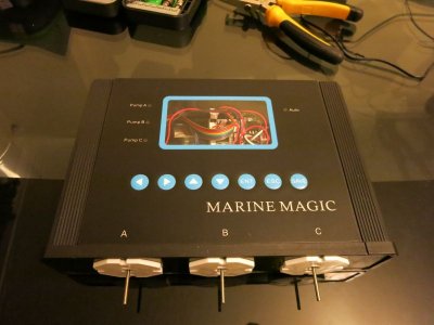
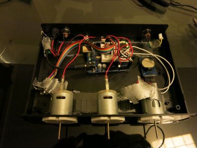
So how does the poor old Marine Magic doser look after it's open heart surgery?? Not too shabby :beer:

From below & on I've described how I built the DIY doser. I have made certain design decisions purely from my own understanding of what is best - if you choose to recreate the doser with modifications please do let us all know what you've changed so all the forum can benefit - but please don't ask me how to program your changes for you ;-)
The cost of the DIY doser is approximately :-
Missing from the list above is a 12v power adaptor - I have borrowed the one from my older doser :dance:
So I have decided to use my favourite hobby microcomputer, the Arduino along with NRF24L01 wireless chips to allow wireless programming.
You'll perhaps have noticed that there are two arduino's on the list above?? One of the Arduino's (which we'll call the "˜doser' arduino from now on) will be used to run the dosing calculations, sequence & activate the peri-pumps.
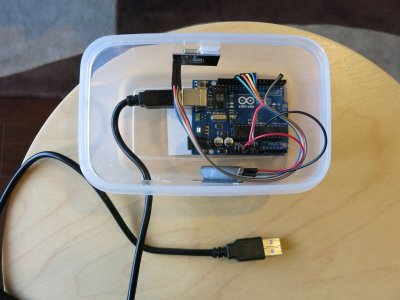
Here's how the 'doser' arduino looks when all wired in :-

The second arduino (which we'll call the "˜programmer') will be solely used to program the doser. In actual fact the programmer took a lot longer to code than the first!
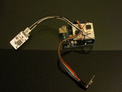
Here's how the programmer looks :-

Before we start programming Arduino's - we need to wire "˜em up first with the various components. The doser arduino requires an NRF24L0, a Real Time Clock (RTC) and a small additional capacitor. In theory you could do without a RTC - but I like it. Wire up the NRF24L01 as-per the excellent guide on maniacbug's (http://maniacbug.wordpress.com/2011/11/02/getting-started-rf24/) website.
The programmer arduino requires an NRF24L01 and a small (~10uf) additional capacitor. Again the NRF24L01 must be wired as-per maniacbug's guide linked to previously.
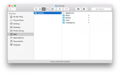
You need to download maniacbug's fantastic NRF24L01 library and install it in your Arduino library folder. Please don't ask me how to do this - please google for the right answer.
You need to download the real time clock library (https://github.com/adafruit/RTClib) and install it in your Arduino library folder
You need to download the fantastic TimeAlarms (http://www.pjrc.com/teensy/td_libs_TimeAlarms.html) library and install it in your Arduino library folder.
The arduino's will run out of RAM unless we use Serial.printf in place of Serial.print as normal. To enable this we must modify print.h (in OS X right click the arduino application, click "˜Show Package Contents' then look under Contents -> Resources -> Java -> hardware -> arduino -> cores -> arduino )
To include the steps shown in http://playground.arduino.cc/Main/Printf section "œadding printf to print class"
Now you're finally ready to go!!
Open up my Transmitter.ino file and upload it to your "˜programmer' arduino (the one without the RTC). Open up my Receiver.ino file and upload it to your "˜doser' arduino.
Now, with your programmer arduino connected to the computer and the dose arduino connected either to your computer or to an external power source
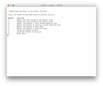
Determine which port to which your arduino is connected and run "˜Putty' on Windows or "˜screen' on OS X (google all that if you don't know how to). Alternative as a poorer but functioning option - Open up the arduino serial monitor and you should be presented with the following list of options :-

Work your way through the dosing options to ensure your aquarium will be dosed correctly.
Now you are ready to build a mini transistor board to function the 12v pumps - this is required to have the 5v arduino function the 12v pumps. The board in-situ is as follows :-

Now, hook your pumps up to your transistor board and your transistor board to the Arduino PWR, GND, 6 &7 pins.
Place this all neatly in a box and glue / stick things so that you don't have any short circtuis or crossed wires and you now have a nice programmable Doser.
:strooper:
- No clunky screen or buttons - wireless Programming via my laptop**
- Doses defined in ml rather than inferred from seconds of pump action **
- Pump calibration to support the above function
- Doses will be automatically spread out over the day in increments defined by the volume dosed **
- Boost Doses can be added, and will be added incrementally along with the next 24hours's dosing **
- Resumes dosing automatically on power failure **
The functions above marked with a ** are all those which my the marine magic doser does not have! Ooh yeah - I forgot that on my DIY doser the clock doesn't reset on a power failure - another improvement over the marine magic unit...
So how does the poor old Marine Magic doser look after it's open heart surgery?? Not too shabby :beer:
From below & on I've described how I built the DIY doser. I have made certain design decisions purely from my own understanding of what is best - if you choose to recreate the doser with modifications please do let us all know what you've changed so all the forum can benefit - but please don't ask me how to program your changes for you ;-)
The cost of the DIY doser is approximately :-
- Arduino UNO clone x2 £13.98
- NRF24L01 Wireless Module x 2 £1.29
- Real Time Clock Module x1 £2.00
- Transistors x 2 £1 (guess - I already had some in my bits box)
- Capacitors x 2 £1 (again a guess)
- Peri Pumps x2 £17.18
- Tupperware Box to House the Doser x2 £5
- TOTAL ~£42
Missing from the list above is a 12v power adaptor - I have borrowed the one from my older doser :dance:
So I have decided to use my favourite hobby microcomputer, the Arduino along with NRF24L01 wireless chips to allow wireless programming.
You'll perhaps have noticed that there are two arduino's on the list above?? One of the Arduino's (which we'll call the "˜doser' arduino from now on) will be used to run the dosing calculations, sequence & activate the peri-pumps.
Here's how the 'doser' arduino looks when all wired in :-
The second arduino (which we'll call the "˜programmer') will be solely used to program the doser. In actual fact the programmer took a lot longer to code than the first!
Here's how the programmer looks :-
Before we start programming Arduino's - we need to wire "˜em up first with the various components. The doser arduino requires an NRF24L0, a Real Time Clock (RTC) and a small additional capacitor. In theory you could do without a RTC - but I like it. Wire up the NRF24L01 as-per the excellent guide on maniacbug's (http://maniacbug.wordpress.com/2011/11/02/getting-started-rf24/) website.
The programmer arduino requires an NRF24L01 and a small (~10uf) additional capacitor. Again the NRF24L01 must be wired as-per maniacbug's guide linked to previously.
You need to download maniacbug's fantastic NRF24L01 library and install it in your Arduino library folder. Please don't ask me how to do this - please google for the right answer.
You need to download the real time clock library (https://github.com/adafruit/RTClib) and install it in your Arduino library folder
You need to download the fantastic TimeAlarms (http://www.pjrc.com/teensy/td_libs_TimeAlarms.html) library and install it in your Arduino library folder.
The arduino's will run out of RAM unless we use Serial.printf in place of Serial.print as normal. To enable this we must modify print.h (in OS X right click the arduino application, click "˜Show Package Contents' then look under Contents -> Resources -> Java -> hardware -> arduino -> cores -> arduino )
To include the steps shown in http://playground.arduino.cc/Main/Printf section "œadding printf to print class"
Now you're finally ready to go!!
Open up my Transmitter.ino file and upload it to your "˜programmer' arduino (the one without the RTC). Open up my Receiver.ino file and upload it to your "˜doser' arduino.
Now, with your programmer arduino connected to the computer and the dose arduino connected either to your computer or to an external power source
Determine which port to which your arduino is connected and run "˜Putty' on Windows or "˜screen' on OS X (google all that if you don't know how to). Alternative as a poorer but functioning option - Open up the arduino serial monitor and you should be presented with the following list of options :-
Work your way through the dosing options to ensure your aquarium will be dosed correctly.
Now you are ready to build a mini transistor board to function the 12v pumps - this is required to have the 5v arduino function the 12v pumps. The board in-situ is as follows :-
Now, hook your pumps up to your transistor board and your transistor board to the Arduino PWR, GND, 6 &7 pins.
Place this all neatly in a box and glue / stick things so that you don't have any short circtuis or crossed wires and you now have a nice programmable Doser.
:strooper:

