DIY Doser

zachts,

I've had a couple of thoughts please note :-

  1. that the atmega chips' eeprom values default to 254 if they've never been written to. Therefore boost dose could dose litres and litres unless you set it to 0 manually before you plug it in to your pumps.
  2. When fresh from the factory your real time clock might not tick over unless you run the appropriate example code from the RTC library first - but then it might tick over just fine. Check the clock is running by querying it a few times at first.

The safe bet is to work your way through the menus and set every single option explicitly
Thanks, I'll keep those points in mind.
 
Getting frustrated now........grrrrrr....

Got everything wired up, less the pumps for testing and for the life of me I cannot get the transmitters to talk to one another. I think it might be a power issue as I'm powering them from my arduino pro mini via a voltage divider to give them the 3.3V they need since they can't handle 5V on vcc according to the info on the transmiters.

I get 3.3v to the transmitter vcc pin until the sketch tries to send something and then the voltage drops to 0.25v.

I tried a separate 5v wall wart to power them with the same result....

I checked and rechecked the wiring and tried going thru the tutorials on maniacbugs page to no avail.

Any pointers to help a guy out?
 
Any pointers to help a guy out?

I suggest getting hold of arduino uno's for both the transmitter and receiver and that should bring you back into simple copy & paste :dance: I've found them on ebay for around $5 a piece - amazing really...

Assuming you've not modified the code at all then it sounds like a power supply issue. Where previous experimenters online have used the radio's they have found the need to run the NRF24L01's from a regulated 3v3 supply. Apparently they draw a fair bit (relatively speaking) of current.

The fact that you are using a potential divider using resistors means you're resisting current flow, and therefore you're seeing your voltage sag under load.

I wish you better luck for today!

edit :- PS, your dosing pumps looks robust as hell - much better engineered than my china doser specials! Like!
 
Thanks! that was indeed the issue, they need a good deal of power relatively speaking. Found a 3.1V wall wart in my box of goodies and that seems to be doing the trick. I have proper regulator in the mail that I plan to use for the final assembly So I can provide power both to the pumps and electroincs from the pumps power supply. (pumps are Welco 24v models, but I run them at 12v so they are less noisy).

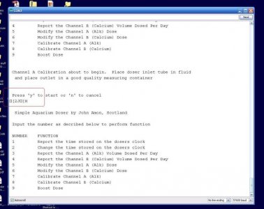
One question though, it seems everything is talking now and I am able to work thru the menus however I get this wierd line of jibberish after every comand is finished (see image) Is that normal? I'm only using the serial monitor for now to do the setup and I do get quite a few "failed" attempts.

Now I just need to get the pumps wired in and clean things up a LOT!
 

Attachments

  • error.jpg
    error.jpg
    61.8 KB · Views: 1
if you use a proper terminal program (I see you're on windows so putty would be a good example) then those odd characters are code to clear the screen and return the cursor to the top - so it works like a proper menu refresh. That's what I meant when I said the ardiuno terminal 'works' but isn't the best.

The failed communications are examples of still not enough power to the radio's I believe. The number of dropped signals should reduce when you get you're proper regulators in place. Although you're using a 3.1v walwart, if there's more than a few inches of cable between the power supply and the actual radios then the voltage will still sag when the radios start communicating. Do you still have the capacitors in parallel (and close by) to the radio VCC /Gnd pins? If not then the capacitors will certainly help.
 
Yes, I still have the Caps in place. Soldered to the pins on the transmitter boards. I don't think it's an issue of not enough current supplied. the transmitters only draw a max of 12.3mA if I read the data sheet right and the wall wart can supply 300mA. However the stability of the voltage might be the issue since it fluctuates a lot from 3.55v to 2.98v when the transmitters are trying to talk, So that probably is accounting for the communication issues.

Just waiting for regulators now. I might snag a couple UNO's as well. You can never have too many on hand :)

Thanks for all your help!
 
Dang it! Got the regulators in today and still no go. Power supply is solid now but I still only get the radios to talk if I'm lucky for the first command, everything after that comes back as failed. Then I have to power down and come back in a few hours and it works for one command and then.....failed......

Is it possible I have bad transmitters?

I think I will go ahead and order up a new pair of transmitters and a pair of UNO's but for now I'm frustrated and putting this project on hold till after the holidays, unless I get really, really board, but I've tried everything now with the components I have right now and no go..........

The only other thing I can come up with is that they may be sitting too close (a few inches apart on my work bench) Would that matter?
 
I've read while working on other projects that your equipment might need to be on a common GND. If you're powering your arduino via one power supply and your radios via another - they may be on seperate GND lines which is no good. I suspect if your radios are transmitting at all then they're fine.

If you have a 5v wallwart or usb wall charger (I used an old iphone charger initially), then power the arduino and radios off the same 5v line, using the regulators you've just had delivered...

Another couple of options as i see it, get a couple of uno's - and in the mean time add capacitors alongside the ones you already added to the radios just in case they aren't getting enough juice.
 
Quick update:

I think I'm in business finally!!!!!!!!

Seems I fried the receiver arduino or shorted something and that's why I was getting frustrated. Replaced it with a new one and all is good :celeb1:

Got it set up on my table right now to let it run for a day or two and make sure everything is ok and accurate.

I think I will need more than 10uf caps though on the final assembly for the radios as if you run too fast thru the menu they loose comunication, so might need a tad more juice from the caps but otherwise all is working at the moment.

Just a side note. Looking thru the code the calibrate section comments say it runs 10 times for 6 seconds, but really it seems to run 5 times for (i count 5 times for 5 seconds, but I probably am counting slow) then it multiplies by 2.

how hard would it be to make the calibration cycle last longer since its only pumping 2.9ml on my setup. I'd get a more accurate calibration with a longer run time for sure since you have to round up or down as decimals aren't allowed.

Next effort is adding a third or fourth channel for dosing Mag and possibly trace elements. That's going to be a hell of a lot of copy paste I think. Might just be easier to run a second receiver (or would they not differentiate each other if both were powered on) I suppose I could program them one at a time though. course having to shut one down eliminates the convenience of boost dose from across the room.

Awesome little project!
 
It's late (twenty to midnight here! And I've been to the pub this 'eve :D ) and i can't face downloading and reading thru the code again, at the mo. But, i would think changing the number of channels and the calibration dose would both be fairly easy coding tasks?

I'll have a look tomorrow, if OP doesn't reply :)

Tim
 
Hi Guys,

Increasing number of channels would be relitively easy, there's just a couple of issues.

  • You'd just need to move to the next available eeprom addresses to store the data for the new channels - be careful here as it's easy to lose sight of which eeprom address is which!
  • currently my menu system will only work up until 10 as it simply responds to a single number input - therefore I'd suggest nesting the doser set functions into a sub-menu, in the same manner as the Boost-Dose sub menu

It's all quite do-able if you're willing to spend the time. If you choose to create a second doser unit entirely, then please be sure to change the addresses or 'pipes' of the NRF24L01 radios in the code first, otherwise they'll cross-talk one another.

Regarding the calibration issue, you can readily extend the pump run-time in code during calibration - however you will need to adjust the math(s) ;) in the dosing functions to account for the change
 
I think I'll try just using two recievers for now.

So if I read everything correct all I'd need to do is change:
const uint64_t pipes[2] = { 0xF0F0F0F0E1LL, 0xF0F0F0F0D2LL };

to this on both receiver and transmitter sketch for programming the second receiver?
const uint64_t pipes[2] = { 0xF0F0F0F0E3LL, 0xF0F0F0F0D4LL };

Then if I get creative and bored write a menu on the transmitter to allow this to be selected by the interface rather than uploading new code.....

thanks for all the help johnamon and for posting this awesome little project!
 
Back
Top