johnamon
New member
zachts,
I've had a couple of thoughts please note :-
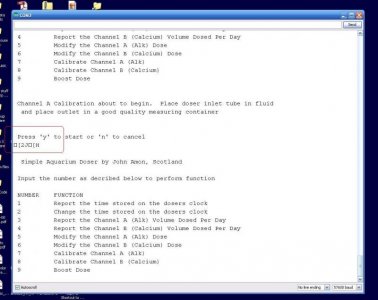
The safe bet is to work your way through the menus and set every single option explicitly
I've had a couple of thoughts please note :-
- that the atmega chips' eeprom values default to 254 if they've never been written to. Therefore boost dose could dose litres and litres unless you set it to 0 manually before you plug it in to your pumps.
- When fresh from the factory your real time clock might not tick over unless you run the appropriate example code from the RTC library first - but then it might tick over just fine. Check the clock is running by querying it a few times at first.
The safe bet is to work your way through the menus and set every single option explicitly
")
 ) and i can't face downloading and reading thru the code again, at the mo. But, i would think changing the number of channels and the calibration dose would both be fairly easy coding tasks?
") in the dosing functions to account for the change
in the dosing functions to account for the change