DIY LEDs - The write-up

Status
Not open for further replies.
I don't want to overdo the blue LEDs so was thinking of not using optics in the aim of getting more spread.

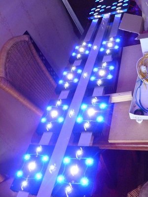
It may sound contradictory, but it seems the RBs don't reach that far down without optics. They - China - gave me 30/40 degree optics instead of 80 degrees and the spotlight effect was clearly visible, as you can see in the picture, so I pulled them off after a few days and that's when I noticed it.

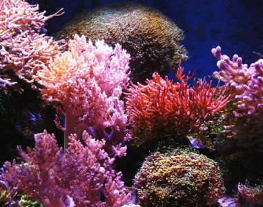
I have a big Nephthea close to the front reaching halfway towards the centre of the tank (the pink softcoral)
In the picture, the optics were still on the LEDs, and there's a little color difference between the top of the coral and the part near the bottom.
Without the optics the part near the bottom looks a lot more brownish like the top left side of the coral.
So I thought that could be due to the XM-Ls which I am using. They are @ 800mA while the RBs are @ 750mA. Dailing down the XM-Ls didn't help much, and dispite the fact that the front row consists of royal blues, like the picture shows, the difference was still clearly visible.
So you might try the RBs without optics, but make sure you have them around when you need them.
 

Attachments

  • Ledlicht aan.jpg
    Ledlicht aan.jpg
    65.2 KB · Views: 2
  • LEDversch.jpg
    LEDversch.jpg
    106.9 KB · Views: 3
Last edited:
Speaking of testing and balancing leds, I just finished doing my royal blues tonight. But I have a question for future reference. How long is too long to run the LEDs off the heatsink at lower MA? Because Im using thermal adhesive to mount my LEDs, I soldered my 2 stings of RB before they are mounted, hooked them up, and balanced them, so I could still easily swap LEDs. But I was wondering as I did it how long is too long? I did it at about 400ma. And turned them up to 990 for a second to double check at full power.
And amazing, My ELN-60-48d will drive 24 Royal Blues at 1000ma! And thats at 9.1v out of the dimming circuit. (I set the internal Pot to 850 though)
 
You can run them about 5 seconds. Then to start taking a big risk with them..

Also, since their Vfs are highly dependent on their operating temperature and you want them balanced in their final thermal situation, I wonder if your heat sink less testing will still even hold once the LEDs are sinked and running at their expected current.
 
So what dyou think ;)

it's worth noting that optics do not give a uniform spread of light in my experience - obviously I haven't tried every optic out there but the ones I have tried dumped most of their light into the central 50% of their rated spread.

More accurately, the spread function seems to be similar to a cosine curve. I haven't measured it, i'm just trying to get across that the spread diagrams you have above may be misleading you. For 60 degree optics, you might be better modeling spreads somewhere between 30 and 45 degrees depending on how much variation you're willing to live with between the spots.

Just my 2p-worth :)

Simon.
 
I figvured I was taking a risk running them off the heatg sink. But i can say this. After about 2 mins at 400ma I could still hold the stars. After I mount them tonight Ill test again and see how they change.
 
Thanks for all the help thus far guys.... I plan on unsing u-channel for my heat sink. Which option would be better for my project? The one on the left which would be open air between each channel or, the one on the right which is channel mounted to a sheet of aluminum?

I'm no expert but I'd just use the U-channel without the sheet. I used 5 72" u-channel rails to make my fixture. It is incredibly simple and works like a champ. Applying gentle airflow across the rails really cools them down nicely.
 
Thanks for all the help thus far guys.... I plan on unsing u-channel for my heat sink. Which option would be better for my project? The one on the left which would be open air between each channel or, the one on the right which is channel mounted to a sheet of aluminum?

I just did a build using u channel and an aluminum plate. Since the dissipation of heat is effected by the surface area of the heatsink, the more surface area the better cooling effect, I figured that adding an aluminum plate to the bottom would increase my surface area and improve cooling.

Mine is a 18x18 heatsink with 72 LED's and no fan (yet), with all of the LED's running at 100% the heatsink only gets to right around 100 degrees. It is warm to the touch, but only a few degrees warmer than commercial fixtures. I may add a fan, but I don't think it is required.
 
it's worth noting that optics do not give a uniform spread of light in my experience - obviously I haven't tried every optic out there but the ones I have tried dumped most of their light into the central 50% of their rated spread.

More accurately, the spread function seems to be similar to a cosine curve. I haven't measured it, i'm just trying to get across that the spread diagrams you have above may be misleading you. For 60 degree optics, you might be better modeling spreads somewhere between 30 and 45 degrees depending on how much variation you're willing to live with between the spots.

Just my 2p-worth :)

Simon.

Thats a good way to look at it Cowboy. i just added 60 degree optics to my fixture which is 36" long and contains 72 LEDs on 120G 4x2x2 tank. The look is very dramatic but the ends are very dim all around the tanks edges and I can clearly see the cone of light coming from the fixture.

Fixture is mounted 8" above the water. I'm considering a way to raise it since I built the canopy to hold the fixture at this height. I really do like the way the tank looks but I think raising it 4" might give me the desired coverage
 
it's worth noting that optics do not give a uniform spread of light in my experience - obviously I haven't tried every optic out there but the ones I have tried dumped most of their light into the central 50% of their rated spread.

More accurately, the spread function seems to be similar to a cosine curve. I haven't measured it, i'm just trying to get across that the spread diagrams you have above may be misleading you. For 60 degree optics, you might be better modeling spreads somewhere between 30 and 45 degrees depending on how much variation you're willing to live with between the spots.

Just my 2p-worth :)

Simon.

You can find data sheets on many of the optics (I know that Carlco has them) that show you the spread.

CJ
 
I can see where doing a sheet of aluminum and U channels adds some surface are for heat dissipation. However, is see a few drawbacks, it means two layers of thermal paste and unless you are using really thick plate I am not sure it will stay tight in the middle with only the ends bolted together. Also the plate does not allow the air to flow as smoothly (no air flow in the center).

I think you would be better off with just the channel, but maybe someone that does this for a living can chime in.
 
@ BMB,

60 degrees would be too narrow for 8" Above the surface. You should read up on FWHM which explains a lot.

From what I understand is that the minimum hight for 60 degree optics is at least 14" to get a reasonable spread.
I'm at 8" too, and except for the blues and the whites in line, which are 2.5" separated, all the LEDs are within 1.7" from each other,
and I'm going to use 80 degree optics. If I had find 90 degree optics I would have used those.
 

Attachments

  • Dist LED.jpg
    Dist LED.jpg
    31.1 KB · Views: 4
Last edited:
@ BMB,

60 degrees would be too narrow for 8" Above the surface. You should read up on FWHM which explains a lot.

From what I understand is that the minimum hight for 60 degree optics is at least 14" to get a reasonable spread.
I'm at 8" too, and except for the blues and the whites in line, which are 2.5" separated, all the LEDs are within 1.7" from each other,
and I'm going to use 80 degree optics. If I had find 90 degree optics I would have used those.

FWHM?

I'm not sure if one could say 8" is too close for 60 degrees as its probably preference depending on what You're trying to achieve. However, I lost a lost of lighting around the edge of the tank but it looks really cool and the color mix is better.

it looks to me though that these 60 degree lenses are 30 degrees to the eye. Same type as you used but came from FEDY. I wonder if the Chinese went 60 degrees from 90 and the result is 30? :eek1: So what was it you had on there that you said looked like 10 or 20 degree lenses? were they 60 also or were they 80?
 
FWHM - Full Width Half Maximum, which basically means that a specific lens has lost 50%of the light at that point, measured in cd.
When the FWHM of an optic is 30 degrees, everything outside that angle is less than 50% of the maximum at the center.
It doesn't say much about the "total" degrees of the lens but generally one can assume that the FWHM it's roughly half the total width. So, I expected an angel of ~40 degrees with bright light from an 80 degree lens, but that turned out to be less than ~20 degrees, the same angle used for a flash light which I used for reference.

Anyway; the new 80 degree optics from the US are at customs at the airport in Amsterdam,
so maybe next week all LEDs have optics again, and then we'll know.
 
Last edited:
FWHM - Full Width Half Maximum, which basically means that a specific lens has lost 50%of the light at that point, measured in cd.
When the FWHM of an optic is 30 degrees, everything outside that angle is less than 50% of the maximum at the center.
It doesn't say much about the "total" degrees of the lens but generally one can assume that the FWHM it's roughly half the total width. So, I expected an angel of ~40 degrees with bright light from an 80 degree lens, but that turned out to be less than ~20 degrees, the same angle used for a flash light which I used for reference.

Anyway; the new 80 degree optics from the US are at customs at the airport in Amsterdam,
so maybe next week all LEDs have optics again, and then we'll know.

Thanks for that. I shall go research it.
 
Finished!

Finished!

Finished my build tonight! Ended up running 36 RB, 14 NW, 5 CW, 5 B. 12 RB are on one lpc-35-700. 5 CW and 5 B on another LPC. 24 RB on a eln-60-48d parallel. And the 14 NW on another eln. I'm very happy with the mix. I can get any range of color I would want. Its all built into a homemade hood. The LEDS are about 9" off the water, 26" off the sand. No optics right now. I may try the 60's I have. Not sure.
led2.jpg


All the electronics mounted on the back. Tied to one power strip so I have an on off switch for all. It doesent give me individual timmer control for colors, but thats fine by me for now.

led1.jpg


Some quick tank shots. Need to spend some time when I'm not so tired To get some better ones. Pics dont 100% represent true tank color. But An idea of the adjustablity even with 24 out of 60 not dimmable.

led3.jpg

led4.jpg

led5.jpg


Right now I like the blues at 100% (about 850ma), and the NW somewhere between 500-700MA. But currently running only the 24 non dimmable mix to acclimate corals.
 
Hi All "“ Need your expertise for a new build.

SPS & LPS Tank is 60" L x 25" W x 26"H

How many LED's would you suggest and combination + degree and should I go with Steve's LED'S or Rapid LED'S.

To cut costs, I don't want to dimm them and would like to place them no more than 10" above the tank.
 
Status
Not open for further replies.
Back
Top