You are using an out of date browser. It may not display this or other websites correctly.
You should upgrade or use an alternative browser.
You should upgrade or use an alternative browser.
DIY Reef Controller
- Thread starter nkd5024
- Start date
nkd5024
New member
I got the boards today! They look beautiful, especially for the price! :celeb1:
I am going to solder one of the up and give it a test. I also finished one of the outlet boxes last night, minus the 2 din 5 connector that still are in the mail.
Hopefully I can finish the other one tonight. Just an fyi the SS relay boards from sainsmart don't fit with 14 gauge wire, which is of course what I bought!
CHeck back in an hour or so for photos!
nkd5024
New member
Warning,
Working with mains voltage can be lethal if not handled properly. If you do not know what you are doing or are even slightly unsure about working with mains power PLEASE consult an electrician. No one on www.ReefCentral.com including myself are liable for anything that you may choose to do.
Outlet Box,
Last edited:


Iceman13579
New member
Wow, that is awesome. My controller consists of me getting my lazy tail out of the recliner and turning dimmer knobs. lol
Hey Nick,
Very impressive so far. I can't wait to get my parts and start building mine. I wanted to be an electrical engineer when I grew up but went a different path. I am still pretty clueless though on how all this stuff goes together. There is a thread on dimming to 0 using an arduino. Do you have this incorporated into this build?
Very impressive so far. I can't wait to get my parts and start building mine. I wanted to be an electrical engineer when I grew up but went a different path. I am still pretty clueless though on how all this stuff goes together. There is a thread on dimming to 0 using an arduino. Do you have this incorporated into this build?
Photobug,
If you are talking about the Meanwell LDD drivers, the PWM output of this controller will work fine with them and/or any driver that accepts a pwm signal.
I have read that the PWM will drop off between 10-11% in terms of dimming. Not that I am sure I need it to go lower than that except to use some blues for moonlights.
I am hoping to contribute what I can on this project. I am more than a bit clueless when it comes to the Arduino, programming and other subjects but have a lot of experience wiring 110V A.C. I am just throwing out an optional way to wire the AC distribution without having to solder. I am getting better at soldering but would prefer to not if I don't have to. Instead of using individual outlets and soldering the connection, I will use traditional dual outlets from Home Depot. You can use either the decorator (rectangular) or the traditional (two roundish) outlets. On back side of these outlets are metal tabs connecting the top and bottom screws. By breaking this tab you can wire the top and bottom outlet separately.
http://electrical.about.com/od/diyprojectsmadeeasy/ss/wiresplitoutlet_6.htm
By keeping the neutral tab intact you can use it to piggy back one to the other by bringing the neutral to the top screw then use the bottom screw to take the neutral out to the next outlet. If you buy a slightly higher end outlet there will be holes in the back for wires as well as screws so you won't even have to curve the wire to fit under the screws, simply insert the wire into the holes and tighten the screws.
To distribute the ground you can use a bus bar or just twist wire connectors to join 4 wires together at a time.
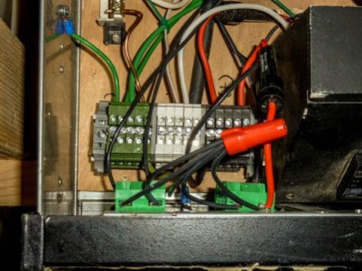
Here is another way to distribute power I found on a build for my brewing rig. I used grounding bars on a previous project to distribute other than ground others (who knew more that me) got upset at my layout so I went with this. http://www.mcmaster.com/#catalog/118/754/=kpeubj
It may be overkill for this project (my brew rig runs 40amps) but I like the way it distributed all 3 sources of power without exposing anything to a possible short. The DIN bar holds the distribution blocks and the individual colors distribute the positive, neutral and ground power sources.
http://electrical.about.com/od/diyprojectsmadeeasy/ss/wiresplitoutlet_6.htm
By keeping the neutral tab intact you can use it to piggy back one to the other by bringing the neutral to the top screw then use the bottom screw to take the neutral out to the next outlet. If you buy a slightly higher end outlet there will be holes in the back for wires as well as screws so you won't even have to curve the wire to fit under the screws, simply insert the wire into the holes and tighten the screws.
To distribute the ground you can use a bus bar or just twist wire connectors to join 4 wires together at a time.
Here is another way to distribute power I found on a build for my brewing rig. I used grounding bars on a previous project to distribute other than ground others (who knew more that me) got upset at my layout so I went with this. http://www.mcmaster.com/#catalog/118/754/=kpeubj
It may be overkill for this project (my brew rig runs 40amps) but I like the way it distributed all 3 sources of power without exposing anything to a possible short. The DIN bar holds the distribution blocks and the individual colors distribute the positive, neutral and ground power sources.
Attachments
nkd5024
New member
I know the dimming will cutout around 15% for my Meanwell ELN-P drivers but I thought that is what was superior about the LDD drivers as they could go down extremely low. To be honest I haven't really looked into this very much as dimming below 10% is super important to me, would be very nice if they could go to zero though.
Using standard outlets was my original plan but the ones I bought were only $14 for all 16 of them so the prices were about the same, and I actually prefer to solder things as I know its not going anywhere.
Using standard outlets was my original plan but the ones I bought were only $14 for all 16 of them so the prices were about the same, and I actually prefer to solder things as I know its not going anywhere.
I know the dimming will cutout around 15% for my Meanwell ELN-P drivers but I thought that is what was superior about the LDD drivers as they could go down extremely low. To be honest I haven't really looked into this very much as dimming below 10% is super important to me, would be very nice if they could go to zero though..
I am adding LEDs to my T5s so would like as many possible options to adjust different strands to achieve sunrises, sunsets and different lighting options and colors. In truth I am pretty lost on that thread in terms of how it is achieved. But it seems for less money you can have more dimming channels with more control. But a number of posters on it are having trouble getting the LDD drivers then getting the expected results so far.
Nick,
Any idea how an LDD driver board would work into your layout?
Using standard outlets was my original plan but the ones I bought were only $14 for all 16 of them so the prices were about the same, and I actually prefer to solder things as I know its not going anywhere.
Kind of the reason I plan on going with standard outlets and wiring. Sticking with what I know best.
nkd5024
New member
It seems that most vendors are sold out of the LDD drivers for the next few weeks. I am planning on switching from my Meanwell ELN drivers to the LDD eventually when I don't have to wait 5 weeks for them to ship.
Basically what you'll have with the LDD drivers is a large power supply that supplies around lets say 48 volts to your LDD drivers. The LDD pwm pin than connects to the output from the arduino. You then would have to connect the grounds from the arduino to the ground from the LDD driver since there isn't a pwm + and -
Basically what you'll have with the LDD drivers is a large power supply that supplies around lets say 48 volts to your LDD drivers. The LDD pwm pin than connects to the output from the arduino. You then would have to connect the grounds from the arduino to the ground from the LDD driver since there isn't a pwm + and -
So if I am planning on using the LDD drivers. I still do not have any LEDs yet anyways.
I am still at a loss how the Arduino ties into the PCBs you have made to then control the LEDs. Will these work in a LDD setup or should I look to designing my own PCBs to make my system work?
I am still at a loss how the Arduino ties into the PCBs you have made to then control the LEDs. Will these work in a LDD setup or should I look to designing my own PCBs to make my system work?
djjester611
New member
I have working Code but for some reason my one relay is not working up to par. Its tank2.
Its the only pin that doesnt turn on at its decided time. Could use a lil help.
//RTC
#include "Wire.h"
#define DS1307_ADDRESS 0x68
byte zero = 0x00; //workaround for issue #527
//LED
int mh = 12; // relay 1
int mhfan = 11; //relay 2
int cfl = 10; //relay 3
int led = 9; //relay 4
int tank2 = 8; // relay 5
int pump1Pin = 5; //relay 7
int pump2Pin = 6; //relay 8
int pump1State = HIGH;
int pump2State = LOW;
long previousMillis = 900000;
long interval = 900000;
void setup()
{
//RTC
Wire.begin();
Serial.begin(9600);
//setDateTime(); //MUST CONFIGURE IN FUNCTION
//LED
pinMode(mh,OUTPUT);
pinMode(cfl,OUTPUT);
pinMode(led,OUTPUT);
pinMode(mhfan, OUTPUT);
pinMode(tank2, OUTPUT); //THIS IS THE RELAY WITH ISSUES:sad2:
pinMode(pump1Pin,OUTPUT);
pinMode(pump2Pin,OUTPUT);
}
void loop()
{
unsigned long currentMillis = millis();
if(currentMillis - previousMillis > interval)
{
previousMillis = currentMillis;
if (pump1State == HIGH)
pump1State = LOW;
else
pump1State = HIGH;
if (pump2State == LOW)
pump2State = HIGH;
else
pump2State = LOW;
digitalWrite(pump1Pin, pump1State);
digitalWrite(pump2Pin, pump2State);
}
printDate();
delay(1000);
}
/*void setDateTime()
{
byte second = 00; //0-59
byte minute = 59; //0-59
byte hour = 00; //0-23
byte weekDay = 3; //1-7
byte monthDay = 14; //1-31
byte month = 3; //1-12
byte year = 12; //0-99
Wire.beginTransmission(DS1307_ADDRESS);
Wire.write(zero); //stop Oscillator
Wire.write(decToBcd(second));
Wire.write(decToBcd(minute));
Wire.write(decToBcd(hour));
Wire.write(decToBcd(weekDay));
Wire.write(decToBcd(monthDay));
Wire.write(decToBcd(month));
Wire.write(decToBcd(year));
Wire.write(zero); //start
Wire.endTransmission();
}
*/
byte decToBcd(byte val)
{
// Convert normal decimal numbers to binary coded decimal
return ( (val/10*16) + (val%10) );
}
byte bcdToDec(byte val)
{
// Convert binary coded decimal to normal decimal numbers
return ( (val/16*10) + (val%16) );
}
void printDate()
{
// Reset the register pointer
Wire.beginTransmission(DS1307_ADDRESS);
Wire.write(zero);
Wire.endTransmission();
Wire.requestFrom(DS1307_ADDRESS, 7);
int second = bcdToDec(Wire.read());
int minute = bcdToDec(Wire.read());
int hour = bcdToDec(Wire.read() & 0b111111); //24 hour time
//int weekDay = bcdToDec(Wire.read()); //0-6 -> sunday - Saturday
int monthDay = bcdToDec(Wire.read());
int month = bcdToDec(Wire.read());
int year = bcdToDec(Wire.read());
//TIME
int time = (hour * 60) + minute;
int time1 = (hour * 60) + minute;
int time2 = (hour * 60) + minute;
int time3 = (hour * 60) + minute;
int time4 = (hour * 60) + minute; //ASSOCIATED ISSUE
//LED's On
if((time >= 0 && time <= 389)||(time >= 1049 && time <= 1440))
{ digitalWrite(led, HIGH); }
else
{ digitalWrite(led,LOW); }
// Actinic on
if((time1 >= 359 && time1 <= 540)||(time1 >= 899 && time1 <= 1140))
{ digitalWrite(cfl, HIGH); }
else
{ digitalWrite(cfl,LOW); }
//Metal Halide Fan On
if(time2 >= 494 && time2 <= 944)
{ digitalWrite(mhfan, HIGH); }
else
{ digitalWrite(mhfan,LOW); }
//Metal Halide On
if(time3 >= 509 && time3 <= 930)
{ digitalWrite(mh, HIGH); }
else
{ digitalWrite(mh,LOW); }
//Tank 2 On ASSOCIATED ISSUE
if((time4 >= 0 && time4 <= 359)||(time4 >= 1079 && time4 <= 1140))
{ digitalWrite(tank2, HIGH); }
else
{ digitalWrite(tank2,LOW); }
//print the date EG 3/1/11 23:59:59
Serial.print(month);
Serial.print("/");
Serial.print(monthDay);
Serial.print("/");
Serial.print(year);
Serial.print(" ");
Serial.print(hour);
Serial.print(":");
Serial.print(minute);
Serial.print(":");
Serial.println(second);
}
nkd5024
New member
Photobug,
The PCB I made has
1) RTC built into it
2) Circuits for connecting either the ETape or Pressure sensor for water level control.
3) Circuit to connect the DS18B20 temp sensor.
4) It also has the circuits to turn the arduino 5v pwm to 10v for the meanwell drivers.
5) Circuits for constant current control over four individual 3watt moonlight leds.
6) break out for the SPI and I2C bus in order to connect multiple things easier.
7) Small circuit to dim the lcd brightness.
8) breakout for 5v power and ground.
Another feature is that the PCB will provide the 20 mA of power to each relay, which the arduino can't handle. You power the PCB with a 12v 1A walwart which than powers itself, all the sensors, and the arduino.
djjester,
I would do a basic test of your relays with a simple turn them all on, wait a few seconds, than turn them all off program. This way you can be sure that its not a hardware issue. It may be that the relays require around 20mA to run and eight of them is really close to the arduino 200mA max output through the I/O pins.
luc.claudel
New member
Hello nkd5024,
Some news concerning the 5" touch screen ???
Luc
Some news concerning the 5" touch screen ???
Luc
luc.claudel
New member
I would love to see a build with a 5 or even
Better A 7" touch screen
i think 5" is ok but 7" you have no library for to use it :spin1:
Similar threads
- Replies
- 0
- Views
- 1K
- Replies
- 2
- Views
- 227