So here's what everyone's waiting for

Pins 1, 2, and 5 go to the Stream Controller's Female DIN5, as designated below:
The Pot in the above schematic will only have two pins connected - namely the middle and one of the side. The other side is not connected to anything.
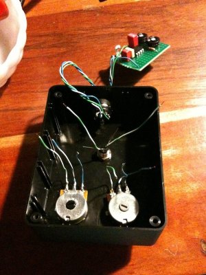
Here is the completed project
Note that the yellow 1K resistor is not on my parts list.. it's the SAME. Just different format (it's my spare components). Also some components were soldered on the other side of the circuitboard (the electrolytic cap for example). The extra resistor here is used for the LED that blinks on and off when the controller pushes the Stream. I will add that to the schematic later.
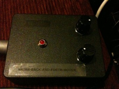
And this is the finished product:
Any questions, please post here and I'll answer them
")
")