Driver question

bblumberg

Member
Hi everyone,

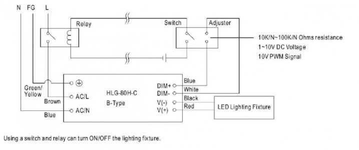
So I am nearing the end of my LED build and have come up on a stumbling point. To recap, I have a 3 x DreamChip 50 build with each channel of the 3 chips connected in series and driven by an individual Meanwell HLG-80H-C700B driver. Everything is neatly tucked into an amplifier case with power to the drivers controlled by a switch and relay wired through thermal sensors that cut the circuit if the chips exceed 65 C. Everything works, chips power up, breaking thermal sensor circuit turns power off, etc.

My problem is that the LEDs only go on at 100% even if the dimming wires are not connected to anything. The drivers will accept variable resistance, PWM or 0-10V signal to control dimming and there appears to be a sensor circuit that discriminates what type of dimming signal is being received. While I haven't hooked this up to my Apex yet (the LED system is still on my workbench), applying 3V (2 x AA cells) to any or all of the dimming circuits has no appreciable effect on the light intensity. What am I missing here? Do I need to put a resistor across the dimming circuit to pull it down before applying the 0-10v signal?

Thanks,
 
When you applied the 3V did you join the grounds together (ie connect the -ve of the batteries to the -ve of the PSU)?

Tim
 
When you applied the 3V did you join the grounds together (ie connect the -ve of the batteries to the -ve of the PSU)?

Tim

Thanks for your reply. No, just applied the + of the battery to the driver blue wire of the dimming circuit and the - of the battery to the white wire of the dimming circuit. Isn't the driver grounded internally?

Fairly similar to this picture except that in my case, the relay is run by a 12v DC circuit that passes through thermal switches that break the circuit if the chip exceeds 65C, cutting power to the driver.
 

Attachments

  • HLG-80H_wiring.jpg
    HLG-80H_wiring.jpg
    24.5 KB · Views: 3
My problem is that the LEDs only go on at 100% even if the dimming wires are not connected to anything.
Shouldn't happen..

Only thing I can think of is you put more than 10V (some of these drivers are quite sensitive to over-voltage) through the dim circuit and burned it out..
 
Shouldn't happen..

Only thing I can think of is you put more than 10V (some of these drivers are quite sensitive to over-voltage) through the dim circuit and burned it out..

The only voltage ever applied across the dimming leads was 3V from 2 AA cells that I commonly use to check LEDs.

Should the 0-10V ground wire be tied to the DC ground for each driver (remember these are pushing as much as 118v DC at 700 mA)? All DC grounds tied together?

Thanks
 
First my apologies.. Got the wrong series ..


These do run "full" w/ an open dim circuit..
Lots of egg on my face here..

Now w/ that embarrassment behind.. don't see any reason your batteries shouldn't work unless they just don't output enough current or some thing to do w/ internal resistance (driver only needs 100 microamps)..


Try a 10k-40k resistor instead.. see if it dims.
Believe it is roughly 10K per 10%

AFAICT.. no no common ground necessary

No worries at all - you know far more than I do about such things. I am happy to see that open dimming circuit gives 100% power since that suggests that what I am seeing is reasonable. I will go to Fry's and grab a few resistors and a potentiometer to play with the dimming circuit.

As far as I can understand from the documentation and what you said about the open dim circuit and 100%, 0V from the Apex should produce 100% output, right? Should I put a 1K resistor across the dim circuit to pull this down to 1% in the absence of voltage from the Apex? Or is this better accomplished some other way?

Thanks for your help!
 
OK, so I bought some 10-100K potentiometers and wired these as variable resistors (ground to middle and + to outside post). 3 channels change intensity when the potentiometer is moved (2 outer white channels and middle violet channel). 2 channels (both of the RB channels, each on a different drivers) show no difference when the potentiometer is connected or not. Some sort of progress, I think...
 
2 channels (both of the RB channels, each on a different drivers) show no difference when the potentiometer is connected or not. .

Odd.
Check to make sure your pots are good..or aren't the wrong resistance or something..

10kOhm resistor would still help troubleshoot this..
Pretty foolproof..
I'd personally just scavange one from "something"
Brown black orange..

10K.gif


resistor-color-code-band.jpg
 
Odd.
Check to make sure your pots are good..or aren't the wrong resistance or something..

10kOhm resistor would still help troubleshoot this..
Pretty foolproof..
I'd personally just scavange one from "something"
Brown black orange..

10K.gif


resistor-color-code-band.jpg

Good idea, thanks.

I don't have any resistors handy (other than 1K ohms that I just bought) but just checked all 5 pots (Philmore PC-26 linear taper) with a multimeter and found that they all function similarly, showing variable resistance up to 100K ohms...
 
OK, out of sheer frustration, I disassembled as much as I could and tested the continuity of all the individual lines from the driver box to the LEDs. They passed and all were as expected (i.e., I did not miswire when soldering wires to plugs and sockets)

Next, I disconnected all of the drivers from their lines to the DreamChip, taking care to cap all of the unused DC lines to and from the drivers. I then connected driver 1 (which previously did not dim) to line 1 of the DreamChip series - nothing at all. Hmm. So next I connected the same driver to line 2 of the dream chip series and voila, it works and dims considerably when I apply 3V. Interestingly the adjacent row of white LEDs is now illuminated very brightly. Same story with lines 3 and 4, they work and dim when applying 3V. However, when I get to line 5, nothing again - no light or change when applying 3V.

Perhaps I miswired the lights when connecting them in series. Trace all wires and they are wired correctly. Test anyway, connect + of line 1 and - of line 5 to driver and nothing. Same with the reverse. This can't be the reason anyway since lines 2, 3 and 4 all work. Go ahead and test all drivers the same way, one by one on each channel. All 5 work perfectly, it is channels 1 and 5 (white channels) on the DreamChip that are not working, irrespective of driver.

My tentative conclusion is that the 2 white channels on the DreamChip have been disabled because they light very, very brightly when any of the middle 3 channels (RB or violet) are powered. Going to check with Alan at AC-RC and see whether this is the case, or whether I should check wiring further.

Oreo57, thanks for your patient help on this!
 
Last edited:
If you have.. like 10 1KOhms.. just put them in series.. Resistance adds..;)

Actually, what I have are 2.7 kOhm resistors. When I put one of these across the dimmer circuit, the brightness drops waay down and I am still able to increase it by applying 3V. See my other post for what I found out regarding the drivers and LEDs.
 
Need to define very brightly since the phosphors in the whites will "glow" w/ the photons produced by the other chips..

One possible problem could be the cumulative V(f)'s of the white channel is too high
You are allotted 43V per chip w/ the max of your driver..

How about trying this:
Just shorten the white channels by one chip (jumper around one chip)
See if they light.
By repeating w/ different pairs you can also eliminate a bad chip.. OR wire one at a time..

The ind. chips can have a wide range of V(f) so your driver could be "out of juice" w/ 3 white in series .. ;)

Be aware that some drivers do have a "minimum" output.. and will go in limp mode if not reached..but most seem to "flash" then.
don't think Meanwells are like this but can't say for sure..Some of the Chinese ones are like this.. Too little V(f) and "blinks"..

This is what you are using (or close)?

EPSI45-100-5CHY.jpg
 
Last edited:
Need to define very brightly since the phosphors in the whites will "glow" w/ the photons produced by the other chips..

One possible problem could be the cumulative V(f)'s of the white channel is too high
You are allotted 43V per chip w/ the max of your driver..

How about trying this:
Just shorten the white channels by one chip (jumper around one chip)
See if they light.
By repeating w/ different pairs you can also eliminate a bad chip.. OR wire one at a time..

The ind. chips can have a wide range of V(f) so your driver could be "out of juice" w/ 3 white in series .. ;)

Be aware that some drivers do have a "minimum" output.. and will go in limp mode if not reached..but most seem to "flash" then.
don't think Meanwells are like this but can't say for sure..Some of the Chinese ones are like this.. Too little V(f) and "blinks"..

This is what you are using (or close)?

EPSI45-100-5CHY.jpg

Very brightly means, very brightly - much brighter than the RB that is being actively lit next to it.

You certainly know your stuff!

I just opened up one of my beautiful waterproof splices and did your experiment and, voila, the white channel now lights and is blindingly bright, even with sunglasses - much more brightly than the passive lighting from the adjacent royal blue. So your theory is correct, the drivers don't have the juice to light up the white channels, even though they are supposedly not using more than 36V each and the drivers can handle more than that.

These are the similar 5 channels 50 DreamChip so what I am lighting on each channel are 30 chips. It is hard to believe that they are drawing more than the 129 v the driver is rated for (at 36v x 3), but the experiment says otherwise.

So what I learned is that these drivers need a resistor across the dimming line to not be at 100% brightness when the dimming power is 0V and that the white channel needs more than the stated Vf to power up. If I had this to do over again, I would probably go with individual LDD-based boards for each chip and suffer the amount of wiring necessary to handle this rather than be clever with the single driver box and few wires to the LEDs. I may eventually do that anyway, but I have spent so much time on this already that it seems much easier to drop in higher voltage drivers for the 2 white channels and put this on my aquarium already. Probably the HLG-80H-C350B will do the job.

Thanks again, your help has made solving this problem possible!
 
Back
Top