Jargrog's LED stupid question thread.

Jargrog

New member
Greetings,
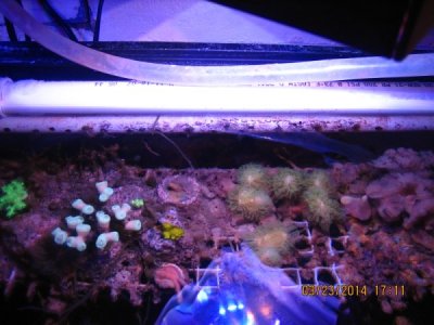
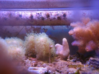
Title says it all. I've spent months reading all the threads I could find (and didn't have enough sense to write things down) so its time to start asking. I'm trying to keep this as simple as possible. I have a standard 125 gallon 72x18x23 tank lit by four 96w power compacts. Its basically a FOWLR with a few zoos/mushrooms/soft corals. It's highly unlikely I'll ever attempt corals that require growing skeletons. The current plan is to replace them with 72 LEDs mounted to aluminum C channel approximately 8 inches above the tank (they will be inside a hood). The glass top will remain on the tank. The tank has two braces across the top effectively dividing it into 3 openings approximately 21.5 inches wide. I'm leaning toward 12 royal blues, 4 true blues and 8 neutral whites per opening running at 700mA, most likely Rebel ES from Steve's. At first I'll see how it looks with no optics (since its hidden inside a hood) but I get the feeling 80 or 90 degree optics is probably a better choice. I am a bit concerned the 2:1 blue/white combination will be a bit too blue (I'm used to a 1:1 ratio blue/10k PC look). Which leads me to stupid question#...
1. I know the closer you space the LEDs the better but how far apart is too far before blending problems occur?
2. If I'm placing 24 LEDs per opening would 4 rows of 6 LEDs or 3 rows of 8 LEDs give better coverage? Or am I just splitting hairs.
3. Placing a LED 1 inch from the tank edge seems unnecessary. How far from the tank edge is a good starting point?
4. The top braces are 2.5 inches wide. Placing a LED directly above one probably isn't the best choice. What's generally considered a good distance from the brace while still illuminating the space below it?

Well, that's it for round one of stupid questions. I predict more will follow. Thanks for any help.
 
1. Generally best to put one of each color very close together and then space out the clusters.
2. I think I would lean toward 3 rows but see below.
3. My suggestion would be to put the front and back rows about 2" from the tank edge and angle them in slightly, not much, just a few degrees.
4. around 6 to 8 inches, probably would be fine with it hanging 8" up (generally space out your led clusters to evenly cover the space in between the braces. So you might have two clusters on each row with 6" to first cluster and 12" between clusters and then 6" back to the next brace if they are 24" apart for the braces.

As to why 3 rows. I would suggest tweaking your light color a bit. If using Steve's LED I'd probably go with this per section of tank for a FOWLER+ a few softies/polyps:
10 RB
5 B
5 NW (5000k)
5 WW (2700k)

arrange them in clusters of 5. with 2 clusters on the front and back row, and one cluster in the middle row.

you may eventually want to add some violets if you start adding more corals.

the warm whites will bring out red's in the tank that would otherwise look a little pale.

Overall I'd imagine this will look roughly 12000k, still plenty white. Depending on what you use for drivers you could snag a few extra whites and a few extra blues to adjust the ratio later if need be. Or just use dimming to do that.

I would not use optics, they are not needed for your setup and you will get much better spread and blending without them. with around 75 LEDs you will find you can grow quite a lot of coral if you wanted to later.
 
It would be worth doing the 3up anti disco chips for the whites and true blues, if you don't need separate channel controll (ie. 1-NW, 1-WW, and 1-B on each chip) This gives much better color mixing of these three colors. then just put a royal blue star on each side next to it.
 
Zachts, thank you for the input.

Clustering seems to be the way most people here seem to suggest, but I originally wrote that method off for two reasons.
1. I couldn't envision how that could be possible using 1.25 inch aluminum C channel for the heat sink. It's simply not wide enough to mount them in any way but a straight line. Although, I suppose butting 3 stars right up next to each other (especially 3-ups) could be considered clustering, albeit a small one.
2. Heat. I didn't think passively cooled C channel could handle clustering.

The only real life example of DIY led aquarium lighting I've actually seen (and touched) is at my LFS. He runs alternating cool white/royal blue cheep Bridgelux at 650mA (700 is their max) approximately 2 maybe 3 inches apart on 1.25 inch C channel and they don't even come close to running anything near hot. Fancy extruded heat sinks and cooling fans are unnecessary. Now If they were Luxeon/Cree 3-ups pushed to 1/1.5 A without any spacing between them could the C channel handle it? I would guess not, but I really don't know.

I like your idea of the 2 white/1 blue 3-up flanked by 2 royal blues. I have two concerns about it though.
The warm white. Yes, they have a nice high CRI, but wouldn't that look too yellow? Or would the blues easily counteract it. I don't want the tank to look too blue, but the toilet water look is even worse :).
Heat. I realize these LEDs can operate at high temperatures (Phillips recommends keeping a junction temp below 136C). Considering water boils at 100C, 136C is friggin hot! Although I'm only planning to run them at 700mA, would the C channel handle having those 5 LEDs packed that close together? I do not want to use fans. Nor do I have a desire to sear flesh from bone if I should accidentally touch it :)

I also apparently can't read a tape measure. They will be 6 inches above the tank, not 8 inches.
 
Yes, your C channel can handle the 3up flanked by two royal blues just fine. The center right behind the 3up will get several degrees hotter than right behind the 1 up stars but at only 700mA aluminum will wick that heat away into the rest of the heatsinks surface area and you will not notice much of a temperature rise compared to a few inchs away from the "linear clusters". Linear cluster like this are about as effective as any other cluster form using star chips as the spacing between diodes can only get as close as the star chips allow.

As long as you have some air flow thru you canopy and the heatsinks are not sealed up in an air restricting space I doubt you will see temps any hotter than 125 degrees Fahrenheit, not very hot at all.

The warm white I mentioned specifically and only the one from Steve's that is 2700k (model: LXW9-PW27) has a pretty heavy red spike and not so much relative yellow. paired with the 5000k white which has the opposite with a large green spike and not a ton of yellow it evens out to be pretty white. Throw in the true blue which whitens it up even more.

Here's a pick of similar I have running over a frag tank which gets minimal maintencance thus the algea but you get the idea of light color. (difference is I'm using a lot of violet, ratio of 3V:1WW:1NW:1B:1RB) It is very white overall. Using the extra Royal Blue instead of violets will make it a bit blue'er as the violets don't add much visually other than coral florescence and par value. (I'm shooting with a 15yr old camera so it pics up a little more blue than in real life, par for the course when photographing LED lit tanks though)
 

Attachments

  • IMG_9620.jpg
    IMG_9620.jpg
    81.8 KB · Views: 19
  • IMG_9625.jpg
    IMG_9625.jpg
    73 KB · Views: 19
Zachts,
Thanks for the pictures. I think I'm going to give your suggestion a try. Looks like I'm going to get a bit more complex then originally planned but I'll probably be happier in the end. I'm thinking of using Meanwell LDD drivers and controlling the NW, WW, B and RB separately with a storm controller. I believe the storm has 6 channels which still leaves me with 2 unused channels for any future additions (such as violets). Calculating 48v- 3v (LDD overhead) / Max forward voltage it looks like I can only fit 13 LEDs per driver (12 for RB) using a 48v power supply. Too bad, 15 would have been easier to wire.
Might be easier if I don't put the WW and NW on separate channels. What do you think, Is there any real value in controlling the NW and WW separately? Also, correct me if I'm wrong, If I end up using 8 LDD 700mA I'll need at least a power supply with 5.6A (8*.7)? Plus a little more for headroom/possible aforementioned violets.
Thanks.
 
Well.........

LDDs are one of the best drivers now a days for DIY, good choice! Storm is a great controler, I use a Storm X on my fancy little build (see my profile, AKA alphabet soup build thread)

Using the LDD you only need to calculate total watts plus 20% overhead so you may still be able to get 15 LEDs running only 700mA! On a smaller supply than you think, My build runs on a 4amp 24volt supply for example and only draws a max of 80 watts roughly at full power with 9 drivers and 8 channels used, plus fans.

It would be strechthing but if you have an adjustalble supply (most are) you can adjust up to around 53 or so volts. (when going over the rated 48 though a higher amp supply is recomeneded due to the extra heat invollved but you don't really use much more power doing this.

I do think controlling warm white and neutral white separately is a good idea if you can. it requries and extra LDD but will let you dial in the over all color much better. You've got the controller channelss and an extra LDD is only $7 or less so do it, IMHO.

Post up your thoughts on layout and wiring and channels and well work it out. The math is really pretty simple when you realize that at lower current the LEDs draw less voltage so if running below MAX and espessially if using Luxeons over Cree, you probably will be able to do strings of up to 15 possibly.

pardon the terrible spelling...... :beer:
 
Ok Zachs, I've crunched some numbers. According to the data sheets from the Luxeon website. Using the maximum forward voltages at 700mA...

15NW x 3.25Vf (max) = 48.75V x .7A = 34.125 Watts
15 WW x 3.25Vf(max) = 48.75V x .7A = 34.125 Watts
15B x 3.51Vf(max) = 52.65V x .7A = 36.855 Watts
30RB x 3.5Vf(max) "“ 105V x .7A = 73.5 Watts

Add that for 178.605 Watts + 35.721 (20% extra) = 214.371 Watts Total. It's unlikely I could find a 215 watt power supply for sale so a single 250watt, 48V, 5.2A power supply should be more then enough to power the 75 LEDs with room to add violets if I should ever chose to do so.

However, I just don't see a way to squeeze 15 LEDs onto a single LDD. Using, for example, the max forward voltage for the blues 3.51 x 15 = 52.65v I would have to pump the max of 56V into the LDD (data sheet note says output V is 3V less then input V) to get it to work. Even the whites can't do it without using the voltage adjustment on the power supply to bump it up 1 volt. Now if I were to use the 'typical' forward voltages in my calculations it might work. Typical Vf for the whites (depending on which table you look at) is 2.9 or 3V. So, 3V x 15 = 45V which would be the max output of the LDD with a 48V input. I suppose it can be done, but it doesn't seem worth the risk. Seems anything less then ideal conditions would be a problem. I'm thinking I'll need to use 2 LDDs each for the NW, WW and Blue (7 on one LDD and 8 on the other) and 3 LDDs for the RB (10 on each). That's how I see it. Am I right or wrong?
 
If using luxeon rebel ES particularly those from Steves LEDs you should be able to get 15. Since they will run lower than max voltage when run at 700mA. You will need to adjust the PSU up slightly to around 54 volts. A 250 watt supply should be enough. You could also just use 14 LEDs on each LDD. losing 5 leds wouldn't make a huge difference though you could just run one extra LDD and make it a combined string, say for Dawn/Dusk effects. You could run 7 to 8 leds also and use a smaller PSU say 30 volts.
 
Zachts, I don't doubt you when you say 15 would probably work, but I think I'll divide them between two drivers. I'm thinking the less voltage I have running through each string of LEDs the safer my dumb/accident prone arse will be. At 7ish dollars apiece a few more LDDs won't break the bank.

That being said, http://www.meanwell.com/search/ldh-45/default.htm . They step up the voltage. Seems I could easily fit 15 LEDs on one of these! I'm guessing they're designed more for the Bridgelux Vero and any other LED that needs 27+ volts.

I need to stop thinking about it and just pick a method and do it. Otherwise I'll never finish this project. So I'm going to stick with my previous plan of 2 LDDs each for the NW, WW and Blue (7 on one LDD and 8 on the other) and 3 LDDs for the RB (10 on each). If I'm not utilizing their full capacity then so be it. I'll consider it room for expansion if I feel the need to add a few more whites or blues.

The local metal dealers wanted $85 for 18' of 1 1/4" C channel and 9' of 3/4" angle. I spent this week scouring the local scrap dealers for something suitable and found exactly what I needed plus a few feet extra for $20. I'm happy about that. Looking at a tape measure 1 ¼ inches doesn't seem like much but now that I actually have 1 ¼" C channel in my hand it sure seems beefier then what I need. Hmmmm, perhaps I should get the 1A LDDs instead of the 700mA? I can dim the 1A but I can't brighten the 700mA. There I go thinking again :(

I now have 9 separate 2' heat sinks mounted inside my hood. They are simply sitting on the 3/4" angle that's spaced 1/8" wider then the heat sinks and can slide fore and aft over the tank. I do not want to have the wiring between the individual heat sinks connected directly to the LEDs so I'm going to attach 2 terminal blocks to each heat sink. I'll connect the LEDs to the terminal blocks and then the terminal blocks to each other. If a LED burns out I can easily remove the 2' section to fix it with a few turns of a screw. Plus I don't want to be yanking the LEDs around by their solder connections. Any suggestions on which terminal blocks (or something better) to use?

What size screws should I use for mounting the 20mm stars? I thought about thermal adhesive but I would prefer the ability to remove them if needed. Plus I already have enough thermal paste for the job. May as well use it.

Thanks again for the input :)
 
Stay with the LDD drivers. those that you posted can exceed safe voltage levels for DIY. Anything under around 54 volts if fine. you'll get a little zap or rather a tingle but nothing life threatening (DO NOT try it on purpose though) .

When you start getting over 60 volts is when it becomes really dangerous. If you use multiple LDDs just use a lower voltage supply or even consider using LDD-L instead of the H and run them on a 36 volt or smaller PSU as dictated by your highest voltage string. If you go higher on the mA only do it on the blues. You'll never need to run whites at full power anyway from the vast majority of peoples experience (you can always swap an LDD out later, as you noticed they are cheap)

Any terminal block will work fine, just get some cheap ones, the white type full isolation ones from radio shack or similar are nice. Just ensure you have a splash gaurd in place below your array, and secure the heat sinks to the angle so they don't slide around while in operation. You don't want a connection coming loose under power, It could blow the LEDs.
 
4-40 machine screws are preferred method, also one can use rivets as sold by Steve's LED (not as removable but still can be drilled out later and much faster on the install) Many also use self threading screws of a similar size and some people even bolt them down using a lock nut and washer. Just be sure not to let the screws touch the solder pads of the LED, use a nylon washer if needed.

Whatever your comfortable with. Drilling and tapping a lot of holes can be tedious but good future proofing and something to keep you busy and out of trouble for an evening or two. :beer:
 
so a single 250watt, 48V, 5.2A power supply should be more then enough to power the 75 LEDs with room to add violets if I should ever chose to do so.

Now if I were to use the 'typical' forward voltages in my calculations it might work. Typical Vf for the whites (depending on which table you look at) is 2.9 or 3V. So, 3V x 15 = 45V which would be the max output of the LDD with a 48V input. I suppose it can be done, but it doesn't seem worth the risk. Seems anything less then ideal conditions would be a problem.

You may want to consider an alternative "surplus" power supply..
http://www.allelectronics.com/make-a-store/item/ps-545/54vdc-5.2a-switching-power-supply/1.html

More food for thought..

You can use 500mA drivers.. AFAICT Meanwell's "boost" voltage till max amp draw.. In this case it will boost till 500mA is reached.. well below 52.65V.They will run cooler and actually more "efficient"...

You mentioned Steves.. the 3W Luxeons there in "white" (one version) spec at.
http://shop.stevesleds.com/Philips-Luxeon-ES-COOL-WHITE-3-Watt-LEDs-Luxeon-ES-white.htm
Luxeons only consume 2.50!!

- Forward Voltage is 2.50V @ 700ma
- Max current - 1000ma

15 @ 2.5 = 37.5V .. Well within your ps/driver parameters

According to this at slightly over 3V you get a 1000mA draw.. 45V for 15 in series...
http://www.philipslumileds.com/uploads/17/DS61-pdf
130/350= .37L/mA 230/700= .33L/mA 310/1000= .31L/mA
Of course you can get more lumen variation just by "bin" differences..

Add heating decreases in efficiency to this and it will be even worse..
Going from 20C to 90C you can "lose" 10% of your light....
I woudn't doubt that LED temp is around 40C w/ passive cooling and the density you have.. just a guess though.. Point is they will be warmer, and less efficient the closer to max current you get.
Of course dimming is always possible so leaving the possibility of 1000mA and dimming by say 25% is "better".. I suppose.

OK I see that you used MAX V which is over 1000mA draw..and you will "theoretically" never need.. w/out using a higher mA driver... It may be able to "handle" 3.5V but in your setup (1000mA driver ) it will not get 3.5V (3.1 actually).

Readjust to this V..3.1
I appreciate anyone correcting any errors in thinking here BTW........... ;)

Same w/ the RB ect.
Forward Voltage is 2.8V @ 700ma, 3.05V @ 1,000ma
 
Last edited:
I can't edit anymore sooo.. add a few volts to the above for losses in the Meanwell drivers
say 4v

52 and 46
 
Thanks for the replies,

Perhaps I should explain where I'm coming up with my numbers. Using the link Oreo57 provided http://www.philipslumileds.com/uploads/17/DS61-pdf . On page 6: Electrical Characteristics at 700 mA for LUXEON Rebel ES, table 4. I interpret that table to mean if you attempt to operate any of those LEDs at 700mA they will require anywhere between 2.5v and 3.25v to light up. I went with the worst case scenario of 3.25v x 15 leds = 48.75v.
http://www.meanwell.com/search/LDD-H/LDD-H-spec.pdf page 1 note 4: Output voltage will always step down by 3v from input DC voltage. So if I use a 48v power supply the most you can get out of a LDD is 45volts. Not enough to cover the worst case scenario of 48.75v. (a 52v input should work though).
Same thought process for the Blue LEDs. http://www.philipslumileds.com/uploads/265/DS68-pdf Page6, Table 3. Note 1 states the blues/royal blues are tested at 700mA. Using 3.51v as the worst case scenario and you end up with 52.65v for 15 leds. That exceeds the Max output voltage for a LDD (52v).

Since I'm a novice I could very well be misinterpreting those tables! But that is my reasoning for why 15 LEDs on 1 LDD may not be such a good idea :) Please correct me if I'm wrong. Even the efficiency graph on page 3 of the LDD data sheet stops at 14 LEDs "“ coincidence?

Zachts, I thought about using the LDD-L and a lower voltage but those fancy little printed circuit boards on the Coralux or LEDGB websites look way to convenient to not use.
I will have a splash guard in the form of a plastic hinged glass top that comes pretty much standard with any tank. There is way too much evaporation in the winter if I don't use them.
I kinda don't want to secure the heat sinks to the angle. I want the ability to slide them back and out of the way for tank maintenance. I suppose I could slap a piece or two of electrical tape on them. That should hold them securely enough while still keeping them removable.

http://www.mouser.com/ds/2/276/0391000912_TERMINAL_BLOCKS-136070.pdf . Are these the kind of terminal blocks you're talking about?

I was considering buying only enough LEDs to do 1/3 of the tank. That way if I didn't like it I could make changes without potentially having a lot of unneeded LEDs left over. However, If I buy them all at once I could easily wire 15 to a string and see if it really will work! DAMN the decisions!

P.S.
I had to change my post to LEDGB because if I spelled out the website name Reefcentral will automatically change it to clay boa when I hit preview post. Weird.
 
First.. w a 1000mA constant current driver your LED potential will not go over 3.1..3.5 is just max before failure..
rbma.jpg


As to 14.. that table is for 48V DC in which is, considering a 4v differential 44V
14x3= 42v 15x3=45V

Over the effective PS output. Increasing 48 to 51V (yes I know not "standard" ) and you would add the last LED to a "chart"..In other words it stops at 14 because of the PS NOT for any other reason as in "max" Led's

your misunderstanding what they are trying to show....

to operate any of those LEDs at 700mA they will require anywhere between 2.5v and 3.25v

Err no... At 700mA there will be a 2.5v potential on the LED..
If you increase the potential (voltage) the LED will draw more current.. going over 700mA.. IF your driver is a 700mA constant current driver you will not get a v any higher..

My understanding of Meanwell tech is that the driver will ramp up the voltage until the circuit is drawing 700mA.. and then hold.. Whatever the LED potential is to create that draw.. is what it is......

In electronics, a constant current system is a system that can vary the voltage across an electronic circuit to maintain a constant electric current. When a component is indicated to be driven by a constant current, the driver circuit is, in essence, a current regulator and must appear to the component as a current source of suitable reliability.

An important usage of constant current power supplies is with LEDs.

http://www.maximintegrated.com/app-notes/index.mvp/id/3256

The circuit of Figure 4d is a high-efficiency inductor-based boost converter configured to regulate current. A low feedback threshold minimizes the power wasted in the current-sense resistor. Because the LEDs are arranged in series, the LED current matches perfectly under all conditions. Current accuracy is determined by the regulator's feedback threshold accuracy and is independent of the LED's forward voltage variation
 
Last edited:
The steves led chips are typically of the lowest voltage bin available so you will get LEDs running at or below the "average" from the data sheet.

most 48v psu's can be adjusted via a potentiometer (screw) up to 54 or more volts (consult data sheet for specifics on how and how much they can be adjusted)

Using cree and luxeon chips from either Rapid led or Steves you will never see 3.5v on an led at 700mA and likely not even at 1000mA!!!!! (well you might get one, but not on average)

LDD data sheet uses typical undisclosed LEDs for testing, so voltage of the chips is unknown (sort of) All the LDD cares about is maximum voltage it can output relative to current rating and the voltage draw of the load be it 1 LED or 20 LEDs (red LEDs you can run over 20 with some chips at low drive current, the LDD doesn't care)

check with the guys on this thread: http://www.reefcentral.com/forums/showthread.php?t=2222702
they may have some spare LDD-L boards available (this thread invented them, other places borrowed the designs and started selling them for a decent profit)

You will want the heatsinks secured some how mechanical. just use a bolt and thumb screw if nothing else, just setting them on you will knock one into your tank eventually I garuntee it. You also don't want to have the connection between LED driver and LED come loose during opperation, that could blow the LEDs. If the voltage supply comes loos e from a driver that's not as big of a deal (assuming driver is mounted to the heatsink also and only voltage supply wires run to each "movable" light strip)

Those are the type terminals I was reffering to. they can easily be cut apart so just find the longest ones that get you the cheapest price per connection and cut them to size.
 
Oreo, thanks for the explanation. Apparently my interpretation of the information on those tables was way off. Looks like I would have been better off looking at the charts a few pages in. I guess 15 leds per LDD really won't be an issue. On that note, using more realistic voltages to calculate total watts needed...
30RB x 2.9v = 87 x .7 = 61 watts
15B x 2.95v = 44.25 x .7 = 31watts
15NW x 2.9v = 43.5 x .7 = 31watts
15WW x 2.9v = 43.5 x .7 = 31watts
add that up for 154watts +20% = 185watts. Looks like I can probably get away with a SE-200-48 power supply http://www.meanwell.com/search/se-200/default.htm . Although I may go with the SE-350-48. That would be more power then I need but the cost is only about $10 more and I won't ever have to worry about being short on power. I realize I could find a cheaper power supply then Meanwell but 20 years of putting computers together taught me to avoid dirt cheep power supplies. Their full of bad voodoo.

Zachs, your probably right about securing the heat sinks. Its unlikely I'll actually need to move them once I find the perfect position. 'Movable' just seems like something potentially useful.
What size wire do you suggest? I think I read in one of these threads someone recommending 22 to 26 AWG between LEDs.

I guess its about time I start ordering some of this stuff.

Thanks again for the input!
 
Zachs, your probably right about securing the heat sinks. Its unlikely I'll actually need to move them once I find the perfect position. 'Movable' just seems like something potentially useful.
What size wire do you suggest? I think I read in one of these threads someone recommending 22 to 26 AWG between LEDs.

Generally I use just a plain old power cord 14-18 gauge to go from PSU to the light fixture supplying voltage to the drivers (if remotely mounted) Then just whatever I have laying around from driver to LEDs, generally I use 22 gauge (only cause it's what I have on hand in bulk from communications cables, but whatever you have on hand between 18 and 26 gauge is fine. 18 and 20 gauge can be a bit clumbsy and stiff to work with sometimes though. Multi-stranded wire rather than solid core is best. Current over 1000mA or long wire runs in excess of a few feet between driver and LEDs use the lower gauge larger wire within that range.
 
Back
Top