Led driver selection help

I don't like screws for this, its time consuming and, especially with less skill, potentially extremely frustrating. Breaking drills or taps in the heatsink is no fun. Then there is still the potential for every screw to ground the string to the heatsink.

What i would use instead is a thermal adhesive, like Arctic Alumina, to adhere the stars to the heatsink. If you ever need to remove a star a wood chisel (or even a sharp flathead screwdriver) and a small tap of a hammer should pop the star off without much trouble. Scraping the residue off the star/heatsink is not too difficult to reuse the spot/star.
 
@Gorgok, I will have a look at those thermal adhesives. Are they strong enough to withstand the weight of the led with the lenses at higher temperatures?

Finally, I came across a ebay link which sells PWM dimmers(manual). Not sure f they can be used o control the intensity till I get hold of my arduino. Even with a arduino, I would prefer using a switch with Auto/manual mode so that I can override the arduino if required....
Check this:
http://www.ebay.com/itm/DC-New-1-8V...882?pt=LH_DefaultDomain_0&hash=item20f143a9b2


There is this another product on ebay much cheaper. But it says 12-24v output. Not sure what would happen if 5v input is supplied.Sounds stupid but in case it can work , le me know. it looks a much stabler enclosure...
http://www.ebay.com/itm/12V-24V-8A-...256?pt=LH_DefaultDomain_0&hash=item4ad8638f18
 
That first one seems interesting. But as you said you would need a switch to toggle from the arduino circuit to this one, when you want to run manually. Its quite heavy duty for the job you plan, handling up to 2A when you really only need a token, but that won't hurt anything.

LEDs and lenses weigh basically nothing. Arctic Alumina thermal adhesive is specced up to 150C, probably holds well past that, but really nothing you want to use it on should get that hot (as it will have fried...). I don't know how much weight it could hold under ideal conditions, but its lots past enough for the miniscule job here. I wouldn't use the stuff for large multichips, like a radion puck or lumia chipset, because it may cause damage to those removing them. Small LED stars is a much smaller surface area, making removal much easier. They do warn that it is a permanent adhesive, but i still find the occasional removal to be very simple.
 
The only problem with the description of the product is that it does not mention the frequency. I think ldds require 100 -1000 hz frequency for the pwm, according to specs. This one does not mention anything. Hopefully it may be operating in a larger bandwidth like 100 to 4khz and so I can use it......
But if it works then it would be a great work saver in terms on amount of arduino code and hardware I have to purchase for web server or tft shield. Even with a tft shield, I think it makes more sense in having a manual rotary switch than the typical digital values we see on arduino tft shields.
 
Guys need quick help regarding heatsink selection. Gonna make the purchase tomorrow.
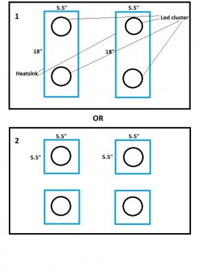
I am planning 4 clusters of 10 leds each(3w). Arranged the leds on paper and it looks like a 5.5" square area is enough for a cluster. Now the question is whether I should go for two heatsink plates each having two clusters, or use four 5.5" x 5.5" square heatsinks and then mount them on a wooden canopy? The reason for keeping four is to keep options open for future, if I wanted to place an additional T5 in between or even increase clusters..... Its quite easy to move those square heatsinks than remove the leds from the heatsink, later.

My only concern is, will the heatsink be able to bear the heat when it is so small? Is there any minimum size recommended for 10x3w led cluster?
Please see attached pic for understanding the two options better.... Thanks in advance.

Sorry I don't have a picture of the heatsink, but they are quite thick with vertical flanges, and not a simple horizontal aluminum plate. Sort of similar to the rapidled heatsink....
 

Attachments

  • led_arrangemenet.jpg
    led_arrangemenet.jpg
    43.2 KB · Views: 3
Sorry but without specific info on the heat sinks you are looking at, it's a bit difficult to give decent advice :(

Generally, two sections of a given heat sink are more effective than one. Find an online site that allows you to see these things (Birmingham Aluminiun in the UK does, not sure of a US site) and you can easily see that 2 separate heat sinks of a given profile, eg 2 lots of 100mm compared with one 200mm is much more effective. Eg:
100mm of this heat sink:
http://www.birminghamaluminium.com/...=100&calc_air_flow=0&update=Update#calculator
Gives 1.47°C per watt
Where 200mm of the same heat sink gives:
http://www.birminghamaluminium.com/...=200&calc_air_flow=0&update=Update#calculator
Gives 1.039°C per watt.

That means, using 10W of heat (ignoring questions about how much energy from LEDs ges in to heat, as that depends very much on how good your LEDs are), one heat sink would increase temp by 10.4C (10x1.039) and two would increase by 7.35°C (as each would only be carrying 5W).

Obviously, you would not be expecting all of the incoming energy to be generated as heat. Some of it, you'd want to be converted to light ;)

Tim
 
Thanks. I got the heatsinks anyway.

Going to start with the led wiring. Is there anything I need to take care of, while wiring the LDD to the led strings? A few points I gathered from other threads:

1. The LDD cannot be fired ON without being connected to the led strings, for testing. It will fry the LDD.

2. The ground for arduino used for PWM has to be common with the led power supply, else the dimming wont work.

3. There is a minimum voltage rating for the LDD and so Min voltage of ldd/ Forward drop of one LED should give the minimum number of LEDs that should be in a string for the LDD to function.

4. Its better to add a drop of solder to the LED points before pasting them on the heatsinks, to make it easier for soldering the wire later.

I ordered some lens attaching paste from LGB called kafuter. Its all written in Chinese and am not sure if there is anything I need to take care of while pasting the lens on the led. Will a small drop be enough to attach? How long do they take to cure fully?

For now, the circuit is gonna work without a PWM input. The driver used is LDD 700HW. Hope they fire at full power without a PWM signal?(Open).

I do have a 12v power supply with me. Can this be used for the Arduino? I read in the specs that 12v is the max. If there is a voltage spike in my home, wouldn't that increase the voltage from 12 to ~14? Should I go for a lower voltage power supply to be on the safer side?

Finally, should the heat sinks be pulling heat away from them or blow cool air onto them? I have seen both and not sure which would be better.....

Kindly add anything which I am missing, or if any of the above 4 points are not valid......
 
Last edited:
Will a small drop be enough to attach? How long do they take to cure fully?
Yes, a little bit is all you need. It's just high-temp silicone, so I'd imagine it would cure in ~24 hours.

For now, the circuit is gonna work without a PWM input. The driver used is LDD 700HW. Hope they fire at full power without a PWM signal?(Open).
Yes, open dimming circuit means 'float high' for LDD.

I do have a 12v power supply with me. Can this be used for the Arduino? I read in the specs that 12v is the max. If there is a voltage spike in my home, wouldn't that increase the voltage from 12 to ~14? Should I go for a lower voltage power supply to be on the safer side?
A spike on the AC side shouldn't spike on the DC side if you don't have a crappy power supply.

Finally, should the heat sinks be pulling heat away from them or blow cool air onto them? I have seen both and not sure which would be better.....
Blow air onto them.
 
That lot looks about right. Min voltage for the LDDs is about 2V so I wouldn't worry about the minimum number of LEDs - it's usually one :)

No idea about curing time for that lens adhesive.

As for blowing onto heat sinks or 'pulling' air away, that depends very much on how you wre going to mount them. If they are enclosed, I'd pull air from the highest point in the case/hood/whatever. Otherwise I'd blow air onto them, personally.

Tim
 
There are numerous ways to test LED's.
A couple I found that are easy:
already connected
Digital VOM.. set to Ohms or Diode, will usually light (dimly) a single LED
not connected generally but optional
3V Lithium battery will light most BUT be very bright and very hot very fast SO be very brief and NOT recommended for low V(f) diodes like red
9V battery can be used to test 3 in series..again briefly.

It is fairly easy to bridge the LED to the heat sink via solder bridges..

After assembly I use the VOM "test" to make sure the LEd is completely isolated from the heat sink by testing the LED neg to heat sink and positive to heat sink and see if it (dimly) lights.

that said a digital VOM and a good soldering iron are almost necessary requirements..
 
For now, the circuit is gonna work without a PWM input. The driver used is LDD 700HW. Hope they fire at full power without a PWM signal?(Open)
Just to add to what jedimasterben said, they will run at full power without a PWM signal so long as the PCB you are using for the LDDs (if you're using one) doesn't have pull down resistors installed (which a lot do)...

Tim
 
Thanks guys. Managed to solder all the LEDs. Got a quick question....
Will it be a no-brainer idea if I used my glue gun to apply a coat of the glue on all the soldered terminals on the led star base? Withe my experience with wires and salt water, they Dont go well very well..... So wondering if he glue gun might help in insulating all electrical points on the led......
 
Fired the LEDs yesterday. Looks super bright......
Happy with the leds for now. Need to figure out the dimming part, once I get the arduino.....

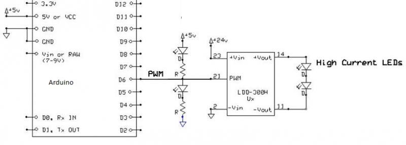
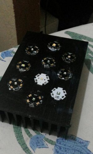
Picked from one of the threads that the arduino needs supporting circuits before it can be connected to the dimming pin of the LDD-700HW. Got the circuit diagram as below. Kindly let me know if this is correct and that its really needed.Also need help with the resistor and diode types mentioned in the circuit...Attaching picture of my leds attached to the heatsink too.....
 

Attachments

  • LDD-300H_PWM_Control.jpg
    LDD-300H_PWM_Control.jpg
    20.9 KB · Views: 3
  • IMG_20141223_163658.jpg
    IMG_20141223_163658.jpg
    42.5 KB · Views: 2
Not sure what that circuit is meant to achieve :confused: All I've ever done is add a pull down resistor to ensure the LEDs are off whilst the arduino boots after a restart.

Tim
 
Not sure what that circuit is meant to achieve :confused: All I've ever done is add a pull down resistor to ensure the LEDs are off whilst the arduino boots after a restart.

Tim

Pick the LED indicator method you want (top or bottom).
For direct drive, the top circuit, Higher PWM (analogWrite) values = brighter output.
For the bottom two, the PWM is inverted, so Lower PWM values = brighter output.

http://forum.arduino.cc/index.php?topic=119825.0

lddcon.jpg


Got me.. give me parts and I'l figure out how to use them.. just don't ask me to build the parts.. ;)
 
Last edited:
Wow. That made my job double complex...... Two diodes and a two resistors? Sorry my understanding of circuits is very low. Do we need two diodes and two resistors? I thought all we need is a pull down resistor..... Is the diode meant to protect the arduino?. And finally what's the +5v before the resistor in the topmost part supposed to do? Is that something which I can just borrow from the arduino power points?my arduino is powered using a 9v supply. But I assume its got 5v power points for devices...
 
I can't see the point of the top circuit. The bottom two both invert the PWM signal (why?). The top one appears to be designed to feed a split voltage into the PWM signal when the arduino PWM is set to zero. But, without something additional, you will also be feeding in that same split voltage (whatever it is based on the value of the resistors you use) into the arduino pin whilst it is set to zero (ie tied to ground) which is surely a bad idea? Never mind the fact that you will not be able to turn off the LEDs.

As i said before, I've always just connected the PWM pin directly to the LDD, but with a pull down resistor. So copy the circuit, remove both diodes, remove the connection and resistor to 5V, put a 10K resistor between the PWM signal and GND :)

Tim
 
That'd do it :)

No pull down resistor there so the LEDs will come on at full power when the arduino restarts, but it has got a resistor to protect the arduino from any feedback from the LDD (not a bad idea).

Tim
 
Back
Top