On moment it's impossible.
But you change a color shown on TFT.
In tab "ferduino" find:
Code:
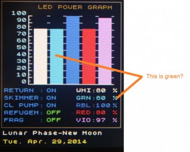
byte cor_canal2[] = {9, 184, 255}; // Azul
Replace this numbers to another combination RGB.
{ red, gree, blue}
No forget to talk that you had problem of hardware not software.
after figuring out that that is where the color set was located, I changed the TFT display from blue to green
and went from,
byte cor_canal2[] = {9, 184, 255}; // Blue
to this,
byte cor_canal2[] = {0, 255, 0}; // Green
as well as change the name display from blue to green, I left all the code the same because I didn't want to screw something up LOL
there's never been any problem with the software, every issue I've had so far has been of my own creation LOL
my wiring up the temp sensors backwards made them inoperable, and my forgetting to remove the 4 pins that control the LCD's built-in SD card reader from the new LCD shield, which made the ethernet shield not want to connect to Joyreef...
and it is plainly stated everywhere this code download is located that not removing those pins will cause problems LOL I just forgot, I do that a lot lately, I must be getting old
")
every issue is and will likely continue to be of my own doing...thankfully, Fernando is a lot smarter than me and was able to troubleshoot my issues from hundreds of miles away LOL
I'm not too much concerned with the LED stuff Fernando, my touch screen shows it as a green channel and I can live with the blue display on Joyreef, I'm using it to control green LEDs, it works great so that's not really a problem
so far this has been a complete joy to build, even with all my screw ups LOL
I'm extremely happy with how this is turning out, I decided to take a few screen shots of all this and post them too
this is just a few screen shots, there's plenty more, but thought I'd share a little of what I see here on my desk top