Loudz34
New member
Pm me and we can chat... or email me.. Loudz34@aol.com
thanks.. Greg
thanks.. Greg
 Today was an interesting day at the Rat Werks.

")

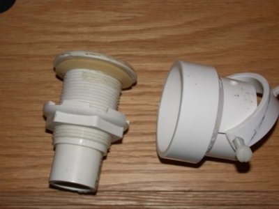
Now all you need is a 1 5/8" hole for the main feed pipe and a 7/16" hole for the Drive-Shaft.
Gregt,") Toutouche,
Toutouche, 

 Ken,
Ken, BRILLIANT!!!!!kstockman said:Toutouche--
Here is a nice way to have clean lines. Have all the water outputs go through bulkhead fittings on the sides of the tank. Then use the version that I came up with and have them attach to the bulkheads.
Even easier--if you have a 1" hole, then extend off the bulkhead about 1" with pipe. Then just use a 1.5" coupling fitting connected up to the motor assembly. The coupling fitting does not even have to be connected to anything if you make the pivot in the correct place. In the end the only thing that you see is a coupling fitting in the tank with a piece connecting it up to the motor shaft. Can't get any cleaner than that. You could do two at either end of the tank. Connecting two up to one motor.
Make sense?
Greg, It'll look great! Major flooding will occur when the sump overflows. Let me explain better. Have a piece of 1" pipe sticking out of bulkhead about 1-2". The nozzle will be 1.5" and will placed such that the 1" pipe sticks into the 1.5" fitting about 1". This will allow enough room for the nozzle to rotate without cutting it (I think). A rod will then go up from the nozzle to the motor housing.