offdahooklikeoj
New member
Hi everyone,
Im finally in the process of building my 120 SPS tank. I have read through about every single manifold design thread on this site and I still cannot decide on how I want to design/build mine.
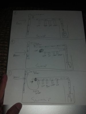
I attached a picture (not well drawn) on the three different designs I have as options. I will have a shut off ball valve and gate valve on each manifold output for carbon, gfo, biopellets/zeovit, etc. Also will have unions, etc for maintenance and possible expansion.
I will be using a Jebao DC12000 as a return pump, I will be using 1.5" pvc for the manifold as much as I can before I reduce it to 3/4" for the display return. The manifold port outputs will be reduced accordingly depending on the reactor.
Im looking for the best possible design from those experienced users, I would like to avoid some issues I read other users have such as gfo reactor flow coming out of whack when turning off other reactors like the carbon reactor.
I look forward to hearing opinions.
Thanks in advance,
Ryan
Im finally in the process of building my 120 SPS tank. I have read through about every single manifold design thread on this site and I still cannot decide on how I want to design/build mine.
I attached a picture (not well drawn) on the three different designs I have as options. I will have a shut off ball valve and gate valve on each manifold output for carbon, gfo, biopellets/zeovit, etc. Also will have unions, etc for maintenance and possible expansion.
I will be using a Jebao DC12000 as a return pump, I will be using 1.5" pvc for the manifold as much as I can before I reduce it to 3/4" for the display return. The manifold port outputs will be reduced accordingly depending on the reactor.
Im looking for the best possible design from those experienced users, I would like to avoid some issues I read other users have such as gfo reactor flow coming out of whack when turning off other reactors like the carbon reactor.
I look forward to hearing opinions.
Thanks in advance,
Ryan
")


")