sandman450f
Premium Member
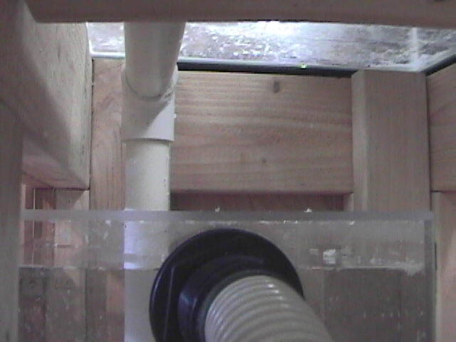
Maybe this will help on the plumbing
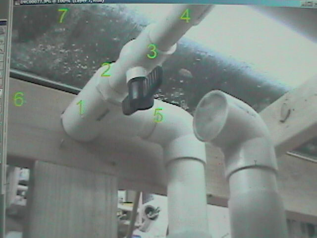
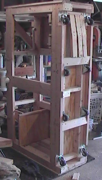
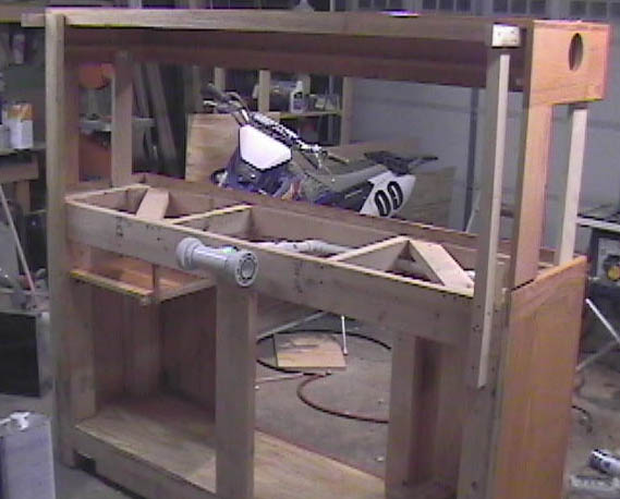
6 and 7 are so you can get a perspective on the inside of the stand. 6 is the inside of the rear horizontal tank support , 7 is the underside of the display tank
1. where the 2" collected o/f drain enters the stand through rear support
2. 1" reducer bushing off the straight portion of the tee
3. ball valve for on/off or flow control to water change tank
4. Supply line to w/c tank. extends forward to inside front of stand, elbows 90deg to the left and ends directly above the top opening on the w/c tank. Then downspout to inside of w/c tank
5. Outlet down to sump
There is more than sufficient flow to the w/c tank simply by the velocity of the water as it hits the reducer bushing, the balance of course drains out the side outlet down to the sump