180 gallon build: Modular control system, 3D printed equipment, open-source

Here's a short video of a mostly complete valve in action.

<iframe width="420" height="315" src="https://www.youtube.com/embed/jRVEJPx6WlM" frameborder="0" allowfullscreen></iframe>

At start up there is a 10 second window where an input (3 second button press) will toggle it into calibration mode. Once in calibration mode it finds the magnet in the large gear from both directions and then waits for user input. Each button press at this point steps the valve one step with the goal being for the user to move it to the full open position. Once full open is reached it will store the offset from the magnet position in EEPROM and use this to find closed each time it auto-homes (via command or on power up/re-start).

Once out of calibration mode, at button press moves the valve open or closed. The opposite of whereever it is currently.

In the end these will be controlled over the serial bus I'm using for all the other modules on the tank.
This is some next level stuff. Been following along and loving it. Keep up the great work.
 
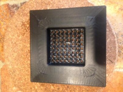
@jr your parts are looking awesome man! No blobs or zits. are you using rafts or overhangs? I've only printed this so far and a few brackets for a frag rack.

I get a distorted top and not very defined plastic netting.

I'm extruding at 90% w/ temps at 235/110
 

Attachments

  • image1.jpg
    image1.jpg
    45.5 KB · Views: 0
Last edited:
@jr your parts are looking awesome man! No blobs or zits. are you using rafts or overhangs? I've only printed this so far and a few brackets for a frag rack.

I get a distorted top and not very defined plastic netting.

I'm extruding at 90% w/ temps at 235/110

Thanks!

Typically I don't use rafts. Not sure on what overhangs are. So I'm guessing I don't use those. I do use support material some time.

In my experience I get ripples on the first layer(s) when either the first layer height is to short or more commonly because it is over-extruding. Getting an accurate measurement of the filament diameter is important; don't assume the filament is actually round or that the diameter is constant. I used to also get ripples on occasion when I used to use glue stick on glass to print on; small glue clumps would cause the ripples to start and then they would just get bigger with each pass of the nozzle.

For the blobs and what not, I get some occasionally but not to much. Air pockets in the filament I think are the likely cause of what I get now. Tweaking retraction settings can help as that can be a common cause. Do you have an option for combing in your slicer? That helps too as it limits where the nozzle can travel over, so when it does ooze its more likely to be in space internal to the print.

And if it makes you feel better I have some parts that I will post soon that I had to print four times to get it right; One run was full of gaps, one the support material couldn't be removed from, one looked like a piece of lava rock as the support material was useless (too far away) and the surface was pushing up into the nozzle.
 
Sorry I didn't explain myself very well - the overhang is the part overhang, so think of arches or semi-circles. You tell the printer at what angle of overhang it should start printing support material. So if I'm printing the roman Colosseum it would have to start printing support material because of the arches - that is a controllable setting in your slicer and was wondering what you had it set at because your parts look complicated but solid.

I'm using a glue stick. Going to try and lay down just one layer and see if that helps. What are you using? Some say hairspray?

I've noticed the diameter inconsistency. Do you just take multiple measurements and average from there?

I'm using simplified 3d I'll check for combing.

Thanks - that does make me feel better because I was thinking of sending it back. Still not getting perfect prints but I managed to print a shot glass that worked well :celeb1:
 
Last edited:
I got my printer after a couple weeks of shipping (i guess the shipper scheduled it on a cheap day instead of letting fedex handle it, or something). Assembly was straightforward enough and got it together the day it arrived. I only ever intended to use abs so i had some on hand, and they included a sample of abs with the thing, so off to printing i go.

After printing a bunch of stuff i still had abs lift at the edges basically no matter what i tried on the aluminum bed. I insulated the bottom of the heater (fiberglass cloth) last night and changed to a ~5mm glass plate (from an aquarium cover) i cut to size and it got better. I also put a cardboard box over it and lowered the thing just a hair more so its almost smearing the first layer and now its printing glass flat pieces that stick all the way to the end. Once cool they pop themselves off. Still using a glue stick before print though not sure if needed (nothing else though). And upped temps to 105C.

So for abs i now run:
Sealed box.
105C bed
230C extruder
.2mm layers 90% first layer
Glue stick on glass
Skirt just to confirm its going to stick and prime nozzle.

Ive been messing with the machine settings, acceleration and print speed and such too. Mine started at 40mm/s print and 400 accel i think. I'm now at 80mm/s with 1600 accel if i understand the numbers right.
 
Sorry I didn't explain myself very well - the overhang is the part overhang, so think of arches or semi-circles. You tell the printer at what angle of overhang it should start printing support material. So if I'm printing the roman Colosseum it would have to start printing support material because of the arches - that is a controllable setting in your slicer and was wondering what you had it set at because your parts look complicated but solid.

Got it. Yes I am familiar with this.

It depends on the object. For something like the cover that goes over the electronics on the ball valves, I started support at an angle greater than 0 degrees and set the x/y offset for support to something near zero. For the valve body, the only support that is needed I included in the model. So it prints with no additional support from the slicer.

Nozzle width and layer height set the theoretical angle at which you should start support.

I'm using a glue stick. Going to try and lay down just one layer and see if that helps. What are you using? Some say hairspray?

I use PET film like this one as a base (PET film) and coat it with a thin slurry of ABS filament dissolved in acetone. Search around for the film. I think when I ordered mine I got 4"x100' roll for like 8$ or 10$. So there are likely much better deals then whats at the link I posted.

I've noticed the diameter inconsistency. Do you just take multiple measurements and average from there?

Yep. And since the internals of the filament and its density are relative unknowns, I will often tweak the diameter I use in the slicer up and down by a few hundredths depending on what the previous print with that filament looked like.
 
One other quick post for now.

I decided the temp controller needed a keypad on board. So I worked something up using some buttons and chip resistors I had on hand (since I don't know what they are, I'm calling the keypad files a beta for the moment: Eagle files). Specific resistor values are not that important, just space the values out.

With a keypad came the need to update how the display is handled and I spent yesterday evening messing with this. Its my first go at building custom characters and I'm eager to show the results.

<iframe width="560" height="315" src="https://www.youtube.com/embed/cvh31RdYecs" frameborder="0" allowfullscreen></iframe>

Here is the Arduino sketch: version 1.2
 
Thats awesome. I am in the process of setting up a 90 RR and will have to put my MendalMax 1.5 to some use I see. That ball valve is crazy cool.
 
My apologize for a slow acknowledgment. I haven't had much opportunity to post the past week.

Thats awesome. I am in the process of setting up a 90 RR and will have to put my MendalMax 1.5 to some use I see. That ball valve is crazy cool.

Thanks. Hopefully some of this winds up useful for you as you get the 90 going.

Your ball valve looks like it operates very well. I like it.

Thanks.
 
I have a few updates:

I printed off a new cover for the temperature controller. It incorporates the new keypad and a few design changes. Reworked SketchUp model is here.
IMG_2117.JPG


Over the past bit I have tweaked (or reworked) the sump plumbing a little and added a couple of valves that should have been there to begin with. I also added a few baffles to the sump. I'm still not settled on the how the sump is setup, but need to get the surge system running before I finalize it. In any case, I don't expect to do any additional full height baffles. So I went ahead and worked up some covers for the input section of the sump and the rubble/filter sock tank.
IMG_2124.JPG

IMG_2123.JPG


Regarding the surge tank, I have the valves plumbed in. I still need to get the power supply worked out (or more put, the input for the higher voltage supply) and work up a temporary controller to coordinate their actions. After that I'll be ready to start running it.
IMG_2125.JPG


As for the biology side of things, the tank has been filled with salt water for about 6 weeks now. Week one there was a major bacterial bloom (the water was milk white). I added some live rock rubble at the start of week two, and the bacteria cleared right up. There were some feather dusters and ball anemones on the rubble and they are still hanging in there. There has been some spreading of diatoms and filamentous green algae, and the coralline on the rubble has colored up a lot (much more intense purple). This past week I noticed many hundreds of copopods on the glass and around the sand. So I think the cycle is going well.
 
This just further emphasizes why I need to quit being lazy and print up my fan mount for my printer so I can get cleaner lines. My printer runs a little to hot so causes things not to square up like I'd like.
 
Help!!!

Help!!!

I'm new to this site but had a qeustion. I have a 150 gallon long tank (5x2x2ft) with built in over flow on one side (two drains one return) first qeustion, I bought the tank for a steal but while bringing it home in my pick up the bottom glass cracked front to back. The sheet that cracked is 3/4 inch annealed and I was wondering can I replace it with 1/2 inch tempered? I already removed the trim and broken sheets of glass. Second qeustion while removing the trim I was very careful since I thought all trim pieces were solid structures but the bottom trim came apart in four sections one section for each side with nice 45 degree cuts to match up, is that normal for larger tanks? The trim did not have any cross bracing either, none were built in it just has the four edge pieces. Last qeustion since it has two drains am I supposed to make each return tube the same height in the overflow? Or does one need to be taller for a reason that I do not know of? As you can tell I'm new to the hobby, any help to fix this tank is highly appreciated! And as far as the glass qeustion no local shops deal with 3/4 inch glass the best I can get is 1/2 inch tempered with holes drilled for $200
Ps. This is actually going to be setup as a freshwater tank with sump and I've never dealt with sumps before but built a pretty decent sump out of an old 55 gallon, learning how to plumb it to the tank now, and when my wife and I buy a house and I learn about saltwater keeping it will then be converted over to a reef tank


I know i'm answering a question exactly the way i hate being answered......(with a suggestion other than the answer i asked for) lol.....but
You can get a nice Brand new 150-180 gallon dual corner Over flow tank for $700 with all new Bulk heads and other bits. I realize thats another $500 but I sure would have a hard time enjoying my aquarium wondering if or when that replacement glass was going to give out. Especially if it wasn't professionally installed by an actual aquarium specialist. Thats a lot of weight and pressure. You may be better off with a little shopping and or searching for another used tank. Maybe sell your broken tank off to someone that doesn't need to fill it with water (reptile home ) Believe me I have been down this road. I get trying to make this hobby as affordable as possible but the tank isnt a place to cut corners. Ok thats my 2 cents
 
I'm new to this site but had a qeustion. I have a 150 gallon long tank (5x2x2ft) with built in over flow on one side (two drains one return) first qeustion, I bought the tank for a steal but while bringing it home in my pick up the bottom glass cracked front to back. The sheet that cracked is 3/4 inch annealed and I was wondering can I replace it with 1/2 inch tempered? I already removed the trim and broken sheets of glass. Second qeustion while removing the trim I was very careful since I thought all trim pieces were solid structures but the bottom trim came apart in four sections one section for each side with nice 45 degree cuts to match up, is that normal for larger tanks? The trim did not have any cross bracing either, none were built in it just has the four edge pieces. Last qeustion since it has two drains am I supposed to make each return tube the same height in the overflow? Or does one need to be taller for a reason that I do not know of? As you can tell I'm new to the hobby, any help to fix this tank is highly appreciated! And as far as the glass qeustion no local shops deal with 3/4 inch glass the best I can get is 1/2 inch tempered with holes drilled for $200
Ps. This is actually going to be setup as a freshwater tank with sump and I've never dealt with sumps before but built a pretty decent sump out of an old 55 gallon, learning how to plumb it to the tank now, and when my wife and I buy a house and I learn about saltwater keeping it will then be converted over to a reef tank

A bit of a derailment, but ok. I would scrap the tank. At this scale you really need to know what you are doing to repair the tank and few people actually do. I'm all for DIY; but not on this one.
 
And for my build I actually have some updates. I know, supper slow to come. Too much travel and other life stuff going on at the moment.

I have the surge system together and have been testing it. Results are pretty good so far. I still have a little tweaking to do on step timing to get a good balance of speed versus torque from the stepper (right now I miss a step or two every now and again, which becomes problematic after a lot of cycles). But I believe this to be a pretty minor issue.

I tried a different ball design to address the step loss issue initially and am uncertain wether I will keep it or not. I added a bridge across the opening; my initial theory was the step loss was caused by the ball opening catching on the seal as it closed on the pressure side of the valve. The new design did help, but a slower step rate helped more. So I am thinking it can all be handled with timing. If you want to see the new ball I updated the SketchUp model I posted earlier with it. If you down load it is there.

Here is a video of one side of the surge triggering. There is not much in the tank, so you really can't see things blowing around. But you can see the reservoir drain and the over flows fill up. The bubbles should go away, right now the out flow side of the valve is not glued so air bleeds in to the plumbing in between cycles.
<iframe width="640" height="360" src="https://www.youtube.com/embed/1Np7cgXKYOQ" frameborder="0" allowfullscreen></iframe>

I also started working on a double dosing pump. This is based off a pump design I found on Thingiverse. The link to the original design is included in the SketchUp model.

Here is the dose module concept. It is designed to mount to Uni-strut and uses a printed version of a strut-nut. The primary application will be for dosing phytoplankton and I will likely model up some bottle holders to go with it.
DoseMod.png


Most of the parts laid out on the work bench:
IMG_2166.JPG


The back side of the control board. It is still missing the battery holder for the RTC. I didn't have one handy so that will have to wait for the moment.
IMG_2181.jpg


And the module partially assembled showing the front of the board:
IMG_2180.jpg


You can get the control board files from here: Eagle files
 
Hi!

You are doing a great job. Congratulations!

I would like to suggest you to create an account on Github or Bitbucket, so you can control all versions of your project and keep all files in one public place.

Best regards.
Fernando Garcia
 
I have to say that is one amazing DIY, Plus all programming and electrical I would have messed everything all up. All of your designs appear to work extremely well together with tons of thought put into them. Never really realized how awesome a 3D printer could be.
 
Back
Top