You are using an out of date browser. It may not display this or other websites correctly.
You should upgrade or use an alternative browser.
You should upgrade or use an alternative browser.
(Another) DIY LED Controller - Simple Arduino Style
- Thread starter katchupoy
- Start date
TheReefNinja
Imagination superfreak
dunno yet people say majijets for em are the best
TheReefNinja
Imagination superfreak
hmmm any clue as to what I should try?
katchupoy
New member
hmmm any clue as to what I should try?
Maxijet with mod on mine. Used it for the past 8 years with natural wave timer... now wave timer is dead and maxijets still works... go figure...
So im using 5v coil relays on mine since january.
Connect it to normally close. So if you happen to have issues with arduino and it does not respond, at least it leave your pump on....
TheReefNinja
Imagination superfreak
not sure I can wire it that way but my return pump is enough for my tank this is just a bonus for it so if something goes wrong then it isnt the end of the world. also I havent had any issues so far lol I knoow I just jinks myself.... I have the relay hooked up to 2 light bulbs as the wave maker so far all night and all day no issues and they keep flashing.
This is the best Arduino reef controller thread I have seen. I am a newbie when it comes to Arduino Programming but I can work with electronics. Thanks to this thread I have built a mock up thats is on the begining stages but I loaded up code last night and it kind of works. I do not have the meanwells I have buckpucks on my leds right now. I know this code is kind of working right now from seeing it control my mocked up led. My question is are there any odifications to the code when using buckpucks? What are the cons to using them? I dont want to buy meanwells because the tank is setup right now with 2 24v powersupplies driving 12 leds 1 ps for blue 1 ps for whites. Thanks to katsup and reef ninja for such a great thread and code.
katchupoy
New member
This is the best Arduino reef controller thread I have seen. I am a newbie when it comes to Arduino Programming but I can work with electronics. Thanks to this thread I have built a mock up thats is on the begining stages but I loaded up code last night and it kind of works. I do not have the meanwells I have buckpucks on my leds right now. I know this code is kind of working right now from seeing it control my mocked up led. My question is are there any odifications to the code when using buckpucks? What are the cons to using them? I dont want to buy meanwells because the tank is setup right now with 2 24v powersupplies driving 12 leds 1 ps for blue 1 ps for whites. Thanks to katsup and reef ninja for such a great thread and code.
Welcome for joining us and RC.
And thank you for your kind words.
1) Modifications on buckpucs?
Im not familiar with buckpucs but if you can give us the voltage requirements for signal then maybe we can help you...
2) With a simple search, I learned that buckpucks are controlled with 5v signal reference. If thats the case, then you dont need the external 10v power supply but instead just use the + and - pins of arduino... thats is how far i can recommend. Im sure that a lot of folks here already did a buckpuck-arduino combo... Im sure they can help us here.
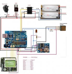
Thanks, yes buckpucks use a 5 volt signal which i am using pwm pin 10. This is a pic of my setup right now. also today i ordered the board w the 4 relays.
Another thing I was wondering if someone can help me out is that I can control the led dimming through the Ctrl pin on the puck but I would also like to shut off the power supply when leds are off.
https://picasaweb.google.com/VicBerto/20110409?feat=directlink
Another thing I was wondering if someone can help me out is that I can control the led dimming through the Ctrl pin on the puck but I would also like to shut off the power supply when leds are off.
https://picasaweb.google.com/VicBerto/20110409?feat=directlink
katchupoy
New member
Thanks, yes buckpucks use a 5 volt signal which i am using pwm pin 10. This is a pic of my setup right now. also today i ordered the board w the 4 relays.
Another thing I was wondering if someone can help me out is that I can control the led dimming through the Ctrl pin on the puck but I would also like to shut off the power supply when leds are off.
https://picasaweb.google.com/VicBerto/20110409?feat=directlink
You can simply put simple mechanical timers on the PS???
Been a long time since i posted your build looks well, This is my new project using info from the links 2 pages back was a bit of a pain to upload and then calibrate the touch screen but all seems sweet
Its an arduino mega 1280 using a 3.2" touch tft and a mega shield with the rtc built in
The first two pics are a sample sketch


Its an arduino mega 1280 using a 3.2" touch tft and a mega shield with the rtc built in
The first two pics are a sample sketch
Last edited:
This was my old arduino 328 with protoshield and nokia 5110 lcd it was using the Krusduino guide but i put 2 extra pwm feeds in one for a fan and the other for uvs leds


These are the leds i will be using

This is one 50w led the spread is around 140deg but i have 90 deg optics

So far have got 4 x 3w violets 4 x 1w uv and 1 x 50w 10k
I am having 6 x 50w and 12 x blue and royal blue, with all these controllable on separate channels i should be able to tailor the look to how i like it
Theres no way i will need to run these anywhere near full i am expecting the 50% max mark
Oh seen people talking about buckpucs these are the ones i have ordered
This is the 10w version it handles 35v @ 1550ma and for £6.00 was the cheapest i could find i have had one running for a around 4 months the led ramps up and down faultless with the arduino
http://cgi.ebay.co.uk/10w-LED-Drive...158?pt=LH_DefaultDomain_0&hash=item19c52b71e6
The same company also does 5w,3w,1w,0.5w drivers all specs are on the ebay pages
These are the leds i will be using
This is one 50w led the spread is around 140deg but i have 90 deg optics
So far have got 4 x 3w violets 4 x 1w uv and 1 x 50w 10k
I am having 6 x 50w and 12 x blue and royal blue, with all these controllable on separate channels i should be able to tailor the look to how i like it
Theres no way i will need to run these anywhere near full i am expecting the 50% max mark
Oh seen people talking about buckpucs these are the ones i have ordered
This is the 10w version it handles 35v @ 1550ma and for £6.00 was the cheapest i could find i have had one running for a around 4 months the led ramps up and down faultless with the arduino
http://cgi.ebay.co.uk/10w-LED-Drive...158?pt=LH_DefaultDomain_0&hash=item19c52b71e6
The same company also does 5w,3w,1w,0.5w drivers all specs are on the ebay pages
Last edited:
One think i cant quite get my head around i have seen some of the built circuits and diagrams using pots why is this, for the arduino provides a 0-5v pwm signal that will go straight in to a buck or if your using a meanwell that requires 0-10v you can just use a ICL7667 this will also stop the arduino pins from been overloaded as the max ma output is around 40ma
This is the schematic using the icl7667 to replace the pots
How do you upload the sketches mines far to big for the site The text that you have entered is too long (41419 characters). Please shorten it to 25000 characters long.
This is the schematic using the icl7667 to replace the pots
How do you upload the sketches mines far to big for the site The text that you have entered is too long (41419 characters). Please shorten it to 25000 characters long.
Attachments
Last edited:
TheReefNinja
Imagination superfreak
The pots are for manual dimming and voltage control in those diagrams. with the proper chips yes we can go potless but I havent gotten that far yet.
Last edited:
katchupoy
New member
I notice that during the leds are on (or ramp up/down), if I do upload, the leds won't continue their job but stay at 0. Is that me, doing something wrong?
I believe this is normal. Since after youre done with the programming you wont touch it anymore.
Please check line 287 if you have these...
PHP:
  /*|||||||||||||||||||||||||||||||||||||||||||||||||||||||||||||||||  L O O P - D I M   F U N C T I O N |||||||||||||||||||||||||||||||||||||||||||||||||||||||||||*/

  byte second, minute, hour, dayOfWeek, dayOfMonth, month, year;
  getDateDs1307(&second, &minute, &hour, &dayOfWeek, &dayOfMonth, &month, &year);
  int daybyminute = ((hour * 60) + minute); //converts time of day to a single value in minutes


  int bluerampup;
     if (daybyminute >= (ontime*60))
       bluerampup = (((ontime*60) + blueramptime) - daybyminute);
     else
       bluerampup = blueramptime;

  int whiterampup;
    if (daybyminute >= (ontime*60 + blueramptime))
       whiterampup = (((ontime*60) + blueramptime + whiteramptime) - daybyminute);
     else
       whiterampup = whiteramptime;

  int whiterampdown;
    if (((ontime * 60) + photoperiod + blueramptime + whiteramptime) <= daybyminute)
      whiterampdown = (((ontime*60) + photoperiod + blueramptime + 2*whiteramptime) - daybyminute);
    else
      whiterampdown = whiteramptime;

  int bluerampdown;
    if (((ontime * 60) + photoperiod + blueramptime + 2*whiteramptime) <= daybyminute)
      bluerampdown = (((ontime*60) + photoperiod + 2*blueramptime + 2*whiteramptime) - daybyminute);
    else
      bluerampdown = blueramptime;
That should catch it if for some reason you have to start or restart arduino in the middle of the scheduled time.
katchupoy
New member
I notice that during the leds are on (or ramp up/down), if I do upload, the leds won't continue their job but stay at 0. Is that me, doing something wrong?
Maybe I mis-understood your question. Here is my question to you.
When you load the sketch to arduino... does the time starts from the beginning? or it continues to be current???
.
katchupoy
New member
One think i cant quite get my head around i have seen some of the built circuits and diagrams using pots why is this, for the arduino provides a 0-5v pwm signal that will go straight in to a buck or if your using a meanwell that requires 0-10v you can just use a ICL7667 this will also stop the arduino pins from been overloaded as the max ma output is around 40ma
This is the schematic using the icl7667 to replace the pots
How do you upload the sketches mines far to big for the site The text that you have entered is too long (41419 characters). Please shorten it to 25000 characters long.
1) ICL7667 - because my knowledge is very limited. Also there are a lot of people there like me who are also have limited knowledge with electronics, programming and arduino.
2) Overload - It will not overload Arduino since we just use it to send signal to meanwell drivers. Not to power them but to send signals.
3) Pots - I kept mine because if I service my arduino. I can simply disconnect the writing to and from arduino. This is where the POTS comes in. Just a redundancy so that you are not fully dependent with Arduino. Manual override.
4) Texts too long - I dont understand this... please explain more.
Similar threads
- Replies
- 6
- Views
- 2K
- Replies
- 2
- Views
- 192
- Replies
- 0
- Views
- 375