chauvet realy pack test issues

omartinez

New member
I just got my chauvet relay pack and i'm running a simple sketch tto turn on off every 10 second channel 1. My issue is that it run great for 30 second then it start to rapidly to turn on off the it stay on.

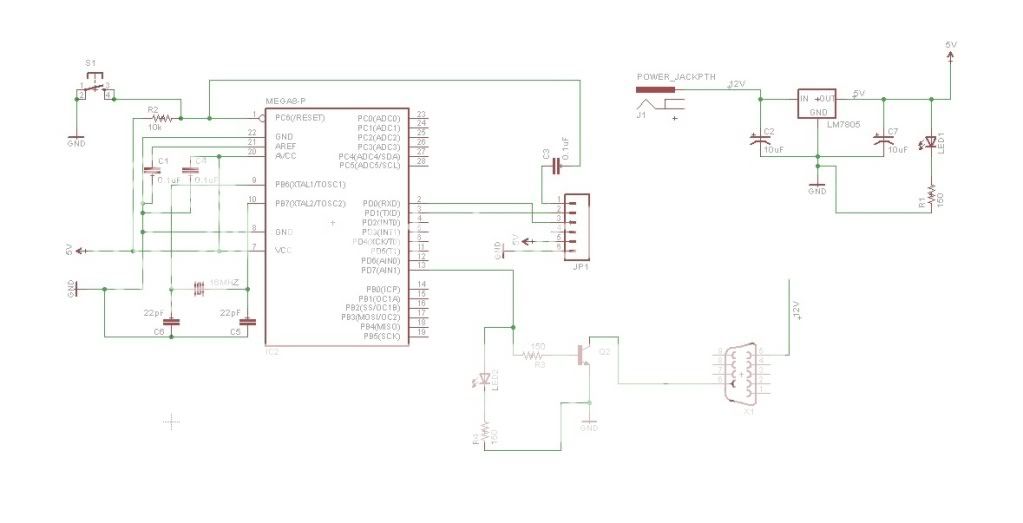
I'm using an atmega328 wired as basic as possible. Using a 18v wall adapter and a 7812 regulator, another 7805 regulator for power to the atmega.
 
I'm using the Chauvet SR-8 with a Mega 2560 and use a ULN2803a in between it works great with NO issues.
 
I'm using the Chauvet SR-8 with a Mega 2560 and use a ULN2803a in between it works great with NO issues.

I'm not using any chip in between right now...I'm planning to use a PCF8574P i've in hand....but for the moment my wiring is like this :

Pin 7 of the ATMEGA connected to a 10k resistor then to a npn transistor then to a female db9 conector and via cable to the chauvet channel 1 along with 12V.

what i'm doing wrong?

maybe connecting directly is the problem?

I notice that after a couple rapid on/off it seems that the ATMEGA freezes at on or off position and i need to reset. Also this only happen when there is something to control connected on the channel.
 
You could be getting some kickback when the relay de-energizes. Put a diode reversed bias across the terminals of the relay and see if that helps.

Otherwise it's really hard to diagnose a circuit that I cannot see and code I cannot read. Post a schematic and some code.
 
You could be getting some kickback when the relay de-energizes. Put a diode reversed bias across the terminals of the relay and see if that helps.

Otherwise it's really hard to diagnose a circuit that I cannot see and code I cannot read. Post a schematic and some code.

there you've

Code:
void setup() {
  pinMode(7,OUTPUT);  


}

void loop() {
  digitalWrite(7, HIGH);   // set the LED on
  delay(5000);              // wait for a second

  digitalWrite(7, LOW);   // set the LED on
  delay(5000);              // wait for a second
  
}

Testpowerbox.jpg


explanation :

as you can see the code is simple.

on the circuit, X1 goes to the chauvet in connector using a db9 male to female cable. LED2 was just added as a visual indication (aside for the clicking noise of the relay). I'm currently using a 12V 1A power supply.
 
ok...i dismantled the breadboard and after some part replacement i've found the problem...

the db( breakout board i was using it's bad, ground was not been shared between the chauvet and the circuit......

thanks for your input....
 
the chauvet uses the shell of the db9 as ground, so you just need to make sure your arduino ground is connected to the chauvet ground.

I too used a ULN2803 and it works fine. the chip costs 37 cents.

btw, the relays on chauvet already have diodes so no need to add more diodes.
 
Hi waverz / d0ughb0y!

I've been reading and planning to use the ULN2803 to handle the Chauvet Relay pack. In your circuits, do you connect the pin 10 of ULN2803 to the 12v source or this is left open (float)? My best guess is that is left open since the relays in the Chauvet already have protection diodes, but want to make sure.
 
you are right that you don't have to connect the common to +12v. Whenever I tested, I did connect the common to +12v and it worked fine. I may connect it in my final circuit. I like the chauvet so much I got two. I am going to put the arduino+ethernet into the first one, and replace the relay board with the smaller 8 channel relay board from ebay, then control the second unmodified chauvet from the first one via the db-9 connection.
 
you are right that you don't have to connect the common to +12v. Whenever I tested, I did connect the common to +12v and it worked fine. I may connect it in my final circuit. I like the chauvet so much I got two. I am going to put the arduino+ethernet into the first one, and replace the relay board with the smaller 8 channel relay board from ebay, then control the second unmodified chauvet from the first one via the db-9 connection.

Thanks for your reply about the common connection! I already ordered some ULN2803A to start playing with them.

Your idea of revamping the Chauvet enclosure is great!!! I bet you will add a small WEB server to the sketch for remote management, sweet!!!
 
I just made the final wiring and if the 12v is connected to 2803 pin 10, the signals are messed up. Good thing i have the 2803 on an IC socket, I just bend out pin 10 to disconnect it from 12v.
 
Back
Top