DIY 12V Koralia Controller

mabviper

New member
I don't know if you guys would find this interesting but I made a diy Koralia Controller. It's only a prototype, a bare system just enough to make a Koralia 12V nano spin.

A little bit of background, I'm a recent Electrical Engineering graduate. Some of my courses involved power electronics and advanced electromechanical systems.

When the Koralia system was launched a year back, I knew it's a project I want to work on. I had a thoery that these power heads had to be AC machines because of how low the price were compared to DC power heads like tunze. After searching the net, I have found no evidence of this. Some people where animate that these were DC while others were AC. Well, after numerous burnt chips, I can put those to rest and say that these are truly AC motors. I have proof.

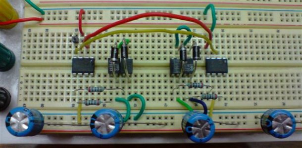
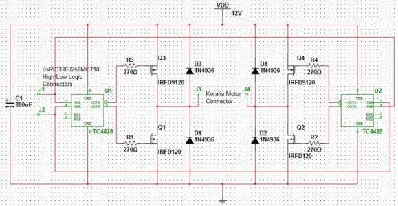
My design consists of a dsPIC33 MCU from Microchip and a simple H-bridge. The dsPIC33 is configured to provide a bipolar PWM gating signal for the H-bridge. I'm running a 10kHz carrier frequency with the AC output signal at 60Hz. I've included a picture of the circuit I used and the schematic for the H-bridge.

Click here for the video of the motor running

Please note though, that this is a proof of concept and by no means do I feel comfortable using it, as-is, for aquarium purposes. Hopefully the next one will be a bit better. If you have any questions, I'll try to answer them as best I can.
 

Attachments

  • protoboard.JPG
    protoboard.JPG
    50.4 KB · Views: 12
  • schematic.jpg
    schematic.jpg
    99.2 KB · Views: 15
Awesome! Bookmarking the thread. I've been hoping someone with an EE background would attempt this, since it's a project I want to do but don't have the background to support on my own.

Any idea on an ETA for the next generation prototype? Or a finished product?
 
mabviper,

Fantastic! Finally another EE-reefer with my interests but more motivation ( young & no children I assume ;-)

I have wanted to do the same with my Rabbit Microcontroller & a "simple" H-bridge.
The rabbit has four hardware PWM channels. I have used them for fan speed & LED dimming, also some AtoD conversions.
I have a Koralia 2 to experiment with sitting in front of me as we speak(type).

I even have all the parts...

So I assume you are using software & PWM to control the sinusoidal current through the H-bridge to the load.

Do you have feed back to measure the voltage &/or current or are you driving it open-loop?

Curious

Stu
 
@der_wille_zur_macht:
I'm not sure when I'll start redesigning the circuit. Right now, I'm still having difficulty choosing the right components for the H-bridge. I know how it works but I'm pretty weak when it comes to actual component selection.

@sturay
Yup, I'm controlling the voltage output and frequency of the h-bridge output w/ the chip. At the moment, my circuit is completely open loop. I figured I should try it open loop first. It's also probably why I burnt tons of mosfets and drivers.... lol.
 
i love reading posts from people that go over my head. looks like a cool project. how many Es does it take to spell geek? jk. my electrical engineer friend from motorola told me that one. all joking aside i like my koralia controlables but would like to be able to run them on a diy if i had to, so thanks for working on this.
 
mabviper,

"Yup, I'm controlling the voltage output and frequency of the h-bridge output w/ the chip."

So, are you just driving each side of the bridge circuit with just a static TTL signal or are you ramping the average current up then down using PWM?
In other words, are you trying to simulate a sinusoid or just a square wave?

One simple way to get close to a sinusoid output using a square wave input to the driver chip is to put a large inductor on the output. This will slow down the rise & fall times.

If you are using PWM you should be able to get it perfect.

" At the moment, my circuit is completely open loop. I figured I should try it open loop first. It's also probably why I burnt tons of mosfets and drivers.... lol."

So you burnt up some FETs.... I see one way that can happen:

Whenever using software to control a circuit of this type, you should have additional safeguards built in. If the software hangs in a bad state & drives BOTH sides at the same time, you will have just built an expensive smoke generator ;-)

You should have some circuitry on the inputs to the FET drivers to guarantee that you cannot drive both sides simultaneously.

Another thing to consider: Sometimes when these types of devices boot up, they can momentarily drive all of the outputs high before the software boots up.

To guard from that, you should have a buffer on the inputs, like an opto-coupler with an enable pin.
Then once software is up & happy, it would enable the buffer chip and allow the drive signals through.

Stu

I realize this is off topic a bit, but isn't this a catch 22? How would you be controlling the enable pin on the opto coupler? Probably with one of the output pins on the controller, right? Well, if they're all blipped at power on, wont the opto-coupler get blipped, too?
 
der_wille_zur_macht,

"Well, if they're all blipped at power on, wont the opto-coupler get blipped, too? "

Good thinking.

One way around that is to use an output pin from the PIC that goes HI to drive the signal that goes into the optocoupler ( an opto input is just an LED )
AND use another output pin from the PIC as the RETURN path for the LED current.

That way, you must drive the enable signal LOW ( the return for the LED ) and the DRIVE signal HI for the LED to output.

That way if all pins glitch the same way on power up, no current flows.

Off Topic, but this is exactly what caused the loss of the WIRE (Wide-Field Infrared Explorer) spacecraft mission.
When the electronics powered up after launch all of the outputs of an FPGA glitched HIGH and blew the protective cover prematurely ( I HATE when that happens ;-)

So one way they keep that from happening, is to spread the ENABLE and the FIRE signals between multiple chips, then stagger the power up sequence so power is not applied to all simultaneously.

Stu
 
@stugray
Oh sorry, I didn't get what you were asking. Yes, I'm using a bipolar PWM gating scheme to recreate a sinusoidal waveform. The dsPIC33 I'm using has hardware motor control features. You can set the deadtime of each gating signal to avoid an h-bridge short. It also has built-in fault detection if the software lags and a short happens. Though, you're right about the state of the pins after power on. Redundant systems is always good, heh.

When I was prototyping it early on, I wasted so many h-bridge pairs and drivers because... i forgot to put a capacitor across the DC link... lol.

Anyways, stugray, maybe you can help me w/ a particular problem, lol. When I test the bridge by placing the 10k resistor instead of the motor, it always ends up w/ a burnt fet. Keep in mind though that when I place the motor instead of the resistor, it'll work.

o.o
 
mabviper,

"When I test the bridge by placing the 10k resistor instead of the motor, it always ends up w/ a burnt fet. "

That doesnt make any sense. A 10K will pull only 1.2 mA. That might as well be an open.

Which FET dies, the high side or the low side? Same one every time?
What are the symptoms of the "blown fet"?
Does it just stop working or is there visible damage?

One thing to keep in mind with FETs, they are very sensitive to ESD.
Are you working on an ESD safe bench & using a wrist strap?

Gate damage due to ESD will show up as losing isolation between the gate & drain/source. A perfect FET should have megaohms between Gate and the other terminals.

Stu
 
I'm probably missing something but this seems pretty complex for the task (my mechanical engineering brain talking). Couldn't you just use an Arduino with a relay to control a 110V pump/powerhead? Is there a necessity to PWM control if I'm not looking to modulate speed?
 
kplagens, the point here is to get variable speed control. I'm hoping we get an update from the OP soon! This has the potential to be a fraction of the cost of a complete off the shelf solution from Koralia or Tunze (not to mention it's open so you can make it behave how you want).
 
I guess I dont have enough experience to understand the desire for variable speed control. If this is used to simulate waves couldn't you select pumps sized for the peak flow desired. Then inertia would drive the transient nature of the wave when the pump starts and stops. If there are times when lower flow is desired then run only one pump. I'm sure I'm missing something.
 
I guess it's a philosophical thing to want totally variable control.

One thing's for sure though - most powerheads not made for variable speed control will behave poorly (start in the wrong direction, chatter for several seconds from time to time, fail in a few months) if switched on and off rapidly enough to simulate waves.
 
What is the recommended hardawre then. Is it the 12V Koralia? Are there others? I would most be interested in an inline pump that would serve the purpose.
 
Most of these projects focus on in-tank powerheads: 12V koralias are cheap, but "hard" to control (this is the only instance of a DIY controller for them that I'm aware of.) Tunze stream powerheads are more expensive, but require only a 0-8v DC signal to control, so it's pretty straightforward.

For an external "inline" pump (i.e. on a closed loop) there's not much out there in the small size range. Your best bet might be a DC pump intended to run on a solar panel for pond fountains, or a DC bilge pump - but it will be hit or miss to find one that's saltwater safe. If you need a large pump, the easiest solution is probably to swap a 3-phase AC motor on a large wet end (one of the Reeflo pumps for example) and then use a VFD to drive it.
 
There is a word outside that Hydor will come out toward the end of 2/2010 with a 1xxx series that was designed for wavemakers at 110V. I run today two K2s/110V AC on a 30 sec. cycle driven by Arduino (on/off cycle) and my 60g cube is fairly happy. I don't think a variable speed will make any noticeable difference, but never had a Vortex so I have no experience.

cheers,
Marian
 
Back
Top