DIY Aquarium Monitor Build

hello and cool idea to keep an eye on your tank setup.. why did you use 2 GPIO and not just one bigger unit for just one usb cable coming out of the control box and going to the computer or was 2 some how more flexible?

Good question! Actually I was going to use the 16 Channel GPIO but since I was starting with someone else's code initially I thought it best to set things up according to a known environment as much as possible. But it does give me some flexibility as well. The code in its current state is very messy with quite a few really looonngg functions. I am currently re-factoring a lot of it so it makes more sense and in doing so I have isolated both cards. I can very easily add a third card should the need ever arise. I can now make a single comment on one line of code to completely prevent one of the cards from reporting. Makes life easier when debugging. And to add... if someone just wants to tinker with the idea they could just buy one 8 channel card and comment out the second card all together.

In the early days of the code the original author only had one card and just expanded as the need grew.
 
Makes more sense to me now my tanks are not near my computer is why I asked about using 1 usb cable what is your thought about using a usb hub to plug the 2 I/O in to then 1 cable from the usb hub it should work I think.
 
Two to one should work fine. Just keep in mind the max distance for a usb cable is 16.4 FT unless you use a powered cable or hub then the max is like 34ft.
 
any updates to how this is going

It was a busy weekend so not a lot of progress. I was having a return pump issue so that took priority.

Just Doing some debugging with the notifications. I have a temp alert that is looping and sending messages every few seconds that I am trying to locate. and looking for a better camera to use. I think I am going to use a network IP camera as opposed to a web cam. The web cam works fine but in my particular case the remote pc is just too far away from where I want to mount the camera.

I've got a trip coming up in a couple of weeks so I need to finish it up.
 
This looks fairly overly complicated... I just finished something similar but arduino based:
ph, sump level, spare water level, temp, adding salinity and lighting schedule

I build a basic web server for it and it spits the results out in json format...or takes GET request commands in json format.

I use a linux box with tomcat to periodically that has a nice front end web pages and database. It makes periodic requests to fill the db for graphs of pH, etc. over time.

For water levels, I just hover some ultrasonic distance meters overhead...Like this one:
http://www.ebay.com/itm/like/331403528989?lpid=82&chn=ps

I considered the arduino along with raspberry pi. Didn't want to do either one. Ultimately this will be ported over and run entirely from my linux server. I really isn't overly complicated.
 
Ok Now that I have corrected my temperature bug I can get back to adding more sensors.

I have the system live again http://mramsey.homeip.net/aquarium

I have moved the pc into my office to continue the use of my webcam at least for now. I was thinking of using an ip camera but at this point I just want to utilize what I have on hand.
 
I added a couple of level sensors. One for the filter socks and one for the skimmer. So far they are working. I received an alert this morning to change the socks. If I had the low level return sensor hooked up I would have been notified that I forgot to turn on the ato solenoid.

https://vimeo.com/119635182
 
Ok seems like videos are not working from tapatalk. At any rate I will be adding more sensors and pics today. The skimmer alarm worked perfectly this morning. I am now working on the return chamber high/low/ok sensor now. I will also have an additional sump level switch for a high condition. So a high condition in the return and a normal condition in the sump would indicate an ATO overfill or pump intake blockage, a high return and high sump indicated return pump not running, low return indicates no ato.
 
AMP Access

AMP Access

Any chance you will be making the code available soon?

PM sent.

If anyone else wants to take a stab at their own copy of the project I will grant access to my local repo by request only right now. Just drop me a PM.
 
Got the sump level sensor in place today. I was having a problem with not returning the level ok status. After hours of debugging the code thinking it was software related, I rechecked the circuitry to discover I had mistakenly soldered in a 100 ohm resistor instead of a 10Kohm. My value would always fall below the threshold that was coded in the software. What did we learn? Always double check the resistor with the meter first.
 
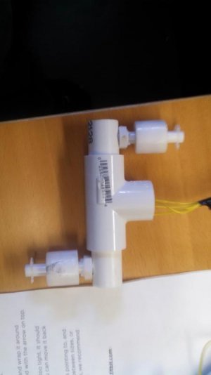
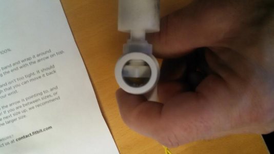
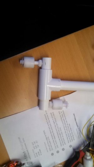
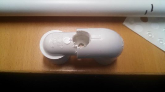
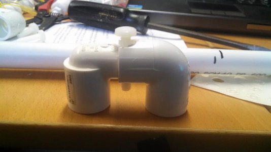
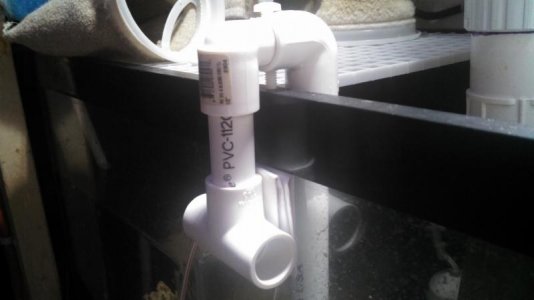
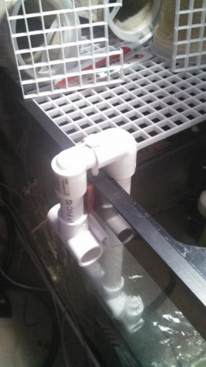
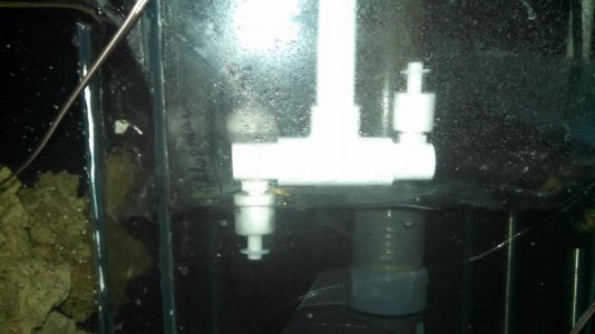
A few pics of the sensors for the sump level...
 

Attachments

  • IMG_20150215_113118_320.jpg
    IMG_20150215_113118_320.jpg
    20.6 KB · Views: 0
  • IMG_20150215_113129_117.jpg
    IMG_20150215_113129_117.jpg
    24 KB · Views: 0
  • IMG_20150215_113321_353.jpg
    IMG_20150215_113321_353.jpg
    25 KB · Views: 0
  • IMG_20150215_121638_951.jpg
    IMG_20150215_121638_951.jpg
    22.5 KB · Views: 0
  • IMG_20150215_121701_168.jpg
    IMG_20150215_121701_168.jpg
    32 KB · Views: 0
A few more...

T added a nylon screw and intentionally made the shaft of the mount about 1/2" long. This gives me about 1" of adjustability to raise or lower the sensors.

I just used 1/2" pvc I had laying around.
 

Attachments

  • IMG_20150215_123125_913.jpg
    IMG_20150215_123125_913.jpg
    27.7 KB · Views: 0
  • IMG_20150215_172230_581.jpg
    IMG_20150215_172230_581.jpg
    45.6 KB · Views: 0
  • IMG_20150215_172243_458.jpg
    IMG_20150215_172243_458.jpg
    41.8 KB · Views: 0
Working on the lighting sensors now. I am going to rewrite the original authors code to simplify it. I want to send a simple Lights ON Lights Off status.

I am also working on a method to log data for 3-7 days and display some nice graphs and visuals on the web side. I am still deciding on how I want to log the data i.e via the AMP application or wholly on the webserver. I do know that I want to log the data on an hourly basis.

On the TO DO list to complete:
1 more light sensors (did I leave the fish room light on?)
DT level sensor
RO storage low sensor
Water mover sensor
 
if you would like to see them in real life here is a link to some one else's page I like his use of them each header is also a link to individual link to that single topic chart
 
Back
Top