DIY LED driver for reef lighting

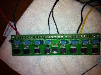
So I built one of the 8 driver Cat4101 boards last night and could not get it to fire up. I haven't tested all the drivers on the board; however, I have one question as I proceed. Do I have to have a PWM signal in order for the circuit to work? Fishman had told me that I could just jump 5v to the signal for now, does this mean just supply 5v from a seperate source other than what's already supplied to the Vin from the onboard 5v? I'm building up a test string from som XR-Es I have laying around so I don't fry my actual tank LEDs.

You can use the 5v signal that's already on the board. The Cat chips should then turn on- if the circuit isn't missing anything else.
 
You can use the 5v signal that's already on the board. The Cat chips should then turn on- if the circuit isn't missing anything else.

Maybe, I am missing something else. I supplied 5v to the PWM A channel from an ac/dc adapter and here are the readings I got.

J1 - 24.1V
Cat4101
1 - 4.57V
2 - 5.03V
3 - 0v
4 - 1.19v
5 - 0v
LED 1+ 1.46V
 

Attachments

  • IMG_1893.jpg
    IMG_1893.jpg
    81.6 KB · Views: 7
Question: I tested the resistance across Rsense to be 600ohm; however, I get nothing when I test continuity across it. Is this normal because of the high resistance? When I test continuity across a .56ohm resistor, it reads normal.
 
Yes it's normal, 600 ohms is too much resistance for a continuity check. On the other hand, .56 ohms is barely any resistance at all, so the continuity check will "beep" when that resistor is tested.
The voltages that you listed for the cats look correct, except for pin #5 . That pin should show what ever voltage remains of your source voltage after the Vf of your led string is dropped. The ideal voltage remaining on that pin should be .5 -.8 volts according to the chips specs. Since you're not seeing any voltage at all, I would suspect an open circuit somewhere in you led string.

I tested each LED individually as well as with my existing drivers and the string lit up, so that ruled out the LEDs for me. Is there any way I could have shorted the chip or can I expect to see different readings if I had? Could the Pot be the culprit?
 
Another question: Reading Fishman's directions, it states that each pin should be tested with an ohmmeter after soldering it to the board. What values should I expect to see? For example: on drivers 1-4, I get a reading of 97.3kOhms on pin 1 of drivers 1 and 2; however, I get a reading of .192Mohm on pin 1 of drivers 3 and 4. All other readings are the same across all four chips and pins.
 
With the led string connected to the driver board, do you measure 24 volts on the positive side of the first led? If not- there's your problem.
I've never seen a Cat chip still produce the 1.2 volts at the sense resistor if the chip had been blown. You may have to wait for "The Fishman" to chime in, and help you out. He designed your particular board, so he knows it inside & out.

No, I was reading 1.46V. How do I correct this?
 
So, as I suspected C4 connecting the Vadj pin to ground was messing up with the PWM. After disconnecting the pin, PWM worked like a charm:

<object width="400" height="225"> <param name="allowfullscreen" value="true" /> <param name="allowscriptaccess" value="always" /> <param name="movie" value="http://vimeo.com/moogaloop.swf?clip_id=27844464&server=vimeo.com&show_title=1&show_byline=1&show_portrait=0&color=&fullscreen=1" /> ******* src="http://vimeo.com/moogaloop.swf?clip_id=27844464&server=vimeo.com&show_title=1&show_byline=1&show_portrait=0&color=&fullscreen=1" type="application/x-shockwave-flash" allowfullscreen="true" allowscriptaccess="always" width="400" height="225"></embed></object>

So I just need to rewire the jumpers on the board to disconnect right before the Vadj and add the pot and the board should be ready.


I use a bench PSU for the testing, but after I'm done, I plan to wire the two 24V potrans PSUs I have for the CATs.

Terahz - what oscilloscope is that?
 
Off on a tangent, as its not really an aquarium light (yet!) i am thinking of, what sort of driver would you need to drive 2-3 3W LEDs off a battery? Say you only need it to have a high, low, and off setting... All i know about these driver stuff i have learned here, so i might as well learn something else now too =D.

LEDs would be XM-Ls or XP-G, but in both cases probably settings like 500-750mA for low and 1000-1500mA for high.

What kinda battery?

Do you care about things like battery life?

Any other restrictions - cost, package size, thermal performance?
 
Either connect the power supply to both 24 volts inputs or connect the LEDs to the other side of the boards. It was designed for two 24 volt inputs (only one drives the 5 volt supply - the one you have connected) so that voltage drop across the CATs can be minimized.

Sorry for the slow response I spent the Holiday with family.

Not a problem on the response time. :)

I have tried hooking up power to both J1 and J9, but no positive results were witnessed. If I'm reading this schematic correct. The + leads on the supplies as well as the LED+ are all connected meaning J1+ is connected to LED+ 1-4 and J9+ is connected to LED+ 5-8. I should be able to test for continuity here and verify there is a connection there correct?
 
Yes, and minus goes back to the pin (1 ?) on the CAT.

From your picture in post 2098. try the following.

1) Move the yellow and black wires over to the connector for LED 5.
2) Connect the +5 coming off the board to both of the PWM on that side (A and C)
 
Just quick question here, has anyone ever tried to put driver and leds on the pcb itself so to avoid all this wiring?? Is it expensive to order a PCB board of let's say 6" x 12"..
I don't have even slightest idea how much would that PCB cost to order that's why I'm asking..
 
Just quick question here, has anyone ever tried to put driver and leds on the pcb itself so to avoid all this wiring?? Is it expensive to order a PCB board of let's say 6" x 12"..
I don't have even slightest idea how much would that PCB cost to order that's why I'm asking..

Most people use FR4 PCBs for drivers but it is vital to use MCPCBs (metal core printed circuit boards) for the emitters. There is no reason you can't put everything on MCPCBs but it would be quite expensive. Check out my build thread, it's probably the closest to what you're looking for.
 
What kinda battery?

Do you care about things like battery life?

Any other restrictions - cost, package size, thermal performance?

Most likely li-ion, though a li-po battery could be neat if done right... 2S and however many in parallel (2-3) and of what size cells gets me enough battery life to last at least 6 hours on the lower setting. It should be a charge before use type deal, rather than emergency backup and always ready to go, so i don't think that really is an issue.

Package wise, the smaller the better, it will be just the board a case and the LEDs and lenses though, the battery will be housed separate. It might even be a cooler idea to go separate LED and housings and board and housing... hmm.

And for the battery, being li- it might need to have a cutoff for undervoltage to prevent battery damage, though i think you can get cells with that built in. Not sure which one is smarter.

Cost wise, i know what a similar thing would cost to buy already made. At roughly 200-250 it seems fairly outrageous for 2 LEDs when i know my lights cost about half of that with 30. Sure the battery eats up a fair chunk of that, but discounting the battery and using component prices of my build i'd come up with $25 as an absolute max for the cost of a unit. Batteries will cost what they will, and I will just have to live with it. Now if this is a feasible price for a 2 XM-L build i am not sure, but i don't think its a huge stretch. For XP-Gs this should be comfortably under that price.
 
Back
Top