You are using an out of date browser. It may not display this or other websites correctly.
You should upgrade or use an alternative browser.
You should upgrade or use an alternative browser.
DIY LED driver for reef lighting
- Thread starter der_wille_zur_macht
- Start date
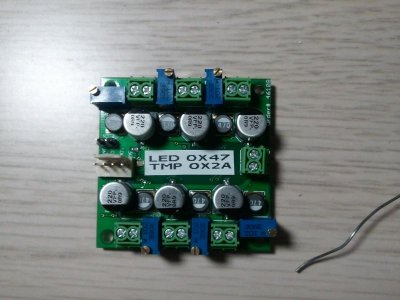
I created a git repo for my PT4115 driver board. It's mostly done now. I'm going to add a power indicator for when it has 5v power from the I2C master then I'll send off to seeedstudio.
https://github.com/brunnels/PT4115_LED_Driver
Drivers are built and tested and I've fixed a couple of small issues with the board layout on github yesterday. The pads were a little small for the power LED so I increased it. I moved one of the decoupling caps away from the PCA9685 chip a little to make it easier to solder. There were 2 typo issue on the silkscreen. One of the TMP421 address pins wasn't connected to ground as it should have been. I moved the mounting holes out a bit to make more room for screws, they were just a gnats *** too close to a couple of the trimmers. Finally I added a couple more ground plane areas where I could for better thermals.
I'm thinking I could go with fewer larger charge pump caps and save some board real-estate. Spec sheet recommends 100uF low ESR capacitor per driver but since they're all on the same bus it might be possible to go with a single 350uF on each side of the board. Spec sheet does specify the charge pump cap should be as close to the driver as possible. Would appreciate der_wille_zur_macht or anyone else's opinion on this.
I've built 2 650mA boards so far and no issues. Also built a 1.2mA board that is working great. Barely gets warm even with a power resistor hooked up for load and all 6 channels going at 1.2mA.
I'm still waiting over a 2 months for some 350mA red leds to come in from HK so I can finish up my Ecoray 60 overhaul. If anyone has 10 on hand they don't need please send me a PM. I have 10 RB's I could trade. I've contacted the seller but it could be another month before I get the re-shipment.
I'll add part sheets for 700mA and 1.2mA builds to the git repo soon. Sourcing most parts from Ebay seems to be the cheapest option especially for the trimmers. There's no problem building for 1.2mA and using the trimmer to dial down to 700mA or even 350mA, but the 700mA parts should be a little less expensive.
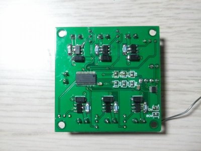
For a 650mA build I'm still debating if ordering the DX drivers in bulk and stripping for parts is the cheapest option. They're fine if you're good with an iron and can pull the parts without getting stuff too hot. I consider myself pretty good with an iron and I still fried a few PT4115 chips and inductors. Might work out better if I built a reflow oven. You'll see a small repair I had to make in the pics where I had to pull off a bad PT4115 chip and killed the DIM pin trace in the process.
Attachments
Landsailor
New member
Great looking board, Kraven! Man, the price of those PT4115 chips is hard to beat! What dimming does your board support?
It wouldn't be too hard to drive it from an Apex with a voltage divider, would it?
My LM3409N samples arrived the other day. They're going to have to sit until I get the tank plumbed and running, though.
It wouldn't be too hard to drive it from an Apex with a voltage divider, would it?
My LM3409N samples arrived the other day. They're going to have to sit until I get the tank plumbed and running, though.
Last edited:
Great look board, Kraven! Man, the price of those PT4115 chips is hard to beat! What dimming does your board support?
It wouldn't be too hard to drive it from an Apex with a voltage divider, would it?
My LM3409N samples arrived the other day. They're going to have to sit until I get the tank plumbed and running, though.
It's an I2C board with 2 I2C devices, LED controller and temperature sensor chip.
The LED controller is 12 bit so can do dimming levels between 1 and 4096. It also supports PWM frequencies between 40hz and 1000hz. Here's the datasheet. http://www.nxp.com/documents/data_sheet/PCA9685.pdf
The temp sensor chip reads the board temp plus it has a jumper to add a simple transistor based external temp sensor. Here's the datasheet for it. http://www.ti.com/lit/ds/sbos398b/sbos398b.pdf
I have arduino libraries for both chips on my github. They're not complete yet but basic functionality is working. I'm currently working on switching them from the Wire library to the much simpler and robust I2C library.
The good thing about I2C is it's pretty universal. There are even USB to I2C adapters you can use to control them with a computer if you wanted.
I've built 2 650mA boards so far and no issues. Also built a 1.2mA board that is working great. Barely gets warm even with a power resistor hooked up for load and all 6 channels going at 1.2mA.
I'll add part sheets for 700mA and 1.2mA builds to the git repo soon. Sourcing most parts from Ebay seems to be the cheapest option especially for the trimmers. There's no problem building for 1.2mA and using the trimmer to dial down to 700mA or even 350mA, but the 700mA parts should be a little less expensive.
All those 1.2mA should actually read 1.2a or 1200mA. Sorry for the confusion. The board pictured is the 1200mA board.
First of all thanks to everyone who has contributed to this great thread...I wont name names as I'm sure ill miss someone. I have spent the last few weeks reading over everything and now feel I'm in a position to start choosing the most appropriate board.
From my research I believe TeraHZ's design with its i2c analogue dimming would be the most appropriate design for my setup as I am aiming for maximum efficiency. There are however two things I'm not sure on; I would like to have the ability to run the LED's at their maximum of 1000ma on occasion however run them at the more efficient level of 700ma the majority of the time, would there be a loss of efficiency in the driver running them at at only 70%? When it comes to wiring the drivers of various max Vin and Ma to a PSU i believe this is done in serial? Do I need any fuses or resistors in line for this setup?
I wish i could contribute to this thread in a more proactive manner but really lack the electronics knowledge to do so. I hope to at least get plenty of pictures together of the final setup to share. Thanks again to everyone, its much appreciated.
der_wille_zur_macht
Team RC
From my research I believe TeraHZ's design with its i2c analogue dimming would be the most appropriate design for my setup as I am aiming for maximum efficiency.
You may already understand this, but keep in mind that particular design is targeted at being dimmed by a microcontroller with I2C capabilities. If you don't have that, you might want one of the other analog-dimming versions.
would there be a loss of efficiency in the driver running them at at only 70%?
Nope. That's the whole advantage of the analog version.
When it comes to wiring the drivers of various max Vin and Ma to a PSU i believe this is done in serial? Do I need any fuses or resistors in line for this setup?
If you're talking about putting multiple drivers on a single PS, you MUST put them in parallel. They all "see" the same input voltage. If you have drivers with wildly different input voltage configurations, you may want to use multiple power supplies. Or, just carefully design the values for the circuit to account for the single Vin.
Let us know some details about your planned setup and we can let you know if it makes sense.
HaKs310
Forever Learning
Hello everybody,
Followed the thread but in the end went the easy way out and bought the assembled Typhon board. I will be receiving my drivers and LEDs soon and wanted to know if I could quick disconnect plugs going from the driver to the Typhon. Would these work?
http://www.amazon.com/gp/product/B005CSTZ9M?ie=UTF8&ref=aw_bottom_links&force-full-site=1
I apologize for the lowly question.
der_wille_zur_macht
Team RC
It might work. There's no way for us to be sure since there are no (meaningful) specifications provided. You'd want to know the current and voltage ratings, gauge of the wire, if it's tinned or not, what type/rating the insulation is, and so on.
Modified TeraHz LED controller with only one Power supply
Modified TeraHz LED controller with only one Power supply
Hello,
during my Linux embedded marelab aqua project I have used TeraHz great work but changed his design a bit because I don't needed and wanted a I2C Bus and 5V connection to each board. I used a 3,3V ZDiode 0,5W to generate the power for the OP to keep Shutdown function.
(For TeraHz: Maybe it can also power the DAC that would keep the 5V power out of the board, depends a bit on the current the DAC uses so the ZDIODE stays under 0,5W and the resistors have to be calculated for the target voltage). My calculations showed that it should save operate between 12V-48V (But be carefull right know its only tested on 12V, test with 42V will follow). Enabled is triggered around 0,05V. In my Design I just wanted to have a input for 0-10V on IADJ pin because it better fits to my centralized D/A solution in my project Linux embeded control project. The benefit is that you just need 3 wires to operate the dimmer in analog mode.

shematic of the addtional parts are in orange, left out the I2C DAC but used the same OP
Maybe someone could use that solution or use it as base idea for a better one to get ride of the 5V cables ..
Marc
Modified TeraHz LED controller with only one Power supply
Hello,
during my Linux embedded marelab aqua project I have used TeraHz great work but changed his design a bit because I don't needed and wanted a I2C Bus and 5V connection to each board. I used a 3,3V ZDiode 0,5W to generate the power for the OP to keep Shutdown function.
(For TeraHz: Maybe it can also power the DAC that would keep the 5V power out of the board, depends a bit on the current the DAC uses so the ZDIODE stays under 0,5W and the resistors have to be calculated for the target voltage). My calculations showed that it should save operate between 12V-48V (But be carefull right know its only tested on 12V, test with 42V will follow). Enabled is triggered around 0,05V. In my Design I just wanted to have a input for 0-10V on IADJ pin because it better fits to my centralized D/A solution in my project Linux embeded control project. The benefit is that you just need 3 wires to operate the dimmer in analog mode.
shematic of the addtional parts are in orange, left out the I2C DAC but used the same OP
Maybe someone could use that solution or use it as base idea for a better one to get ride of the 5V cables ..
Marc
You may already understand this, but keep in mind that particular design is targeted at being dimmed by a microcontroller with I2C capabilities. If you don't have that, you might want one of the other analog-dimming versions.
I am in the process of putting together a Arduino Duemilanove controller. The programming side of things is the most challenging at this stage but in time I hope to have a working sketch.
Let us know some details about your planned setup and we can let you know if it makes sense.
.
Taking your advice into account i have divided my 9 channels into 2 PSUs;
PSU 1:
(i) 18.6Vf @ 1000ma
(ii) 26.4Vf @500ma
(iii) 22Vf @ 500ma
(iv) 24Vf @ 700ma
(v) 31Vf @ 1000ma
PSU 2:
(i) 6.2 @ 1000
(ii) 12.4 @ 1000
(iii) 7.4 @ 700
(iv) 4.8 @1000
How close together in Vf should i be trying to group my channels? Alternatively to the above i could use 4 PSUs to get slightly closer Vf's
Thanks in advance for looking it over, hopefully their is something other noobs like me can get from these questions. :beer:
TheFishMan65
New member
PSY, I don't understand. Is each one of those a string or an LED type. The Vf of each string must be exactly the same for each power supply. If they are LEDs then you couly do 12 votls and 2 type i, 1 type ii, and 3 type iv and be close. The type iii maybe 2, but may not as brightas you think.
mkart
Active member
Any chance we could get a link list of current revs? I have spent a lot of time over the last week pouring through this thread and all its great info. You guys have done great work here. I think for many just finding this thread it would be very helpful to list a few of the most up to date revs. To bad you can't create a sticky inside a thread. I am just getting into playing around with this and have a lot of misc parts to work with. I have meanwells, 24v supplies, a few of Steve's cat4101 drivers and a large assortment of LEDs from various vendors. Now I need to start building panels, actually started last night. The LM3409 looks like a better option for me than the cat4101's that I have but am not sure where the latest rev is. Any help would be appreciated. I have not played with this for years, It's fun to re-learn this stuff.
The LM3409 looks like a better option for me than the cat4101's that I have but am not sure where the latest rev is. Any help would be appreciated. I have not played with this for years, It's fun to re-learn this stuff.
I think the latest LM3409 revs can be found here. I did hear someone mention a 0.7 rev but Im yet to find it. Iv been hoping for a DIP version in the future....fingers crossed.
PSY, I don't understand. Is each one of those a string or an LED type. The Vf of each string must be exactly the same for each power supply. If they are LEDs then you could do 12 volts and 2 type i, 1 type ii, and 3 type iv and be close. The type iii maybe 2, but may not as brightas you think.
Thanks for the reply. Each one of those is/was a LED string all of the one color. The reason i was hoping to have each color on the same string is the ability to fine tune the ratios. Ill get back to the drawing board :facepalm: and see whether i can get some identical strings together.
miamiaquarium
New member
looks really good
TheFishMan65
New member
PSY, That is what I thought. Each string (on the same driver) needs to have identical Vfs. That voltage may/will run different current depending on the type of LED. For a small variation you could use some 0.1, .05. and 1 ohm resistors to eat up some of the voltage, but this may cause issues if the driver supports dimming.
Landsailor
New member
I think the latest LM3409 revs can be found here. I did hear someone mention a 0.7 rev but Im yet to find it. Iv been hoping for a DIP version in the future....fingers crossed.
I just spoke with a phone rep from AVNet. They have no Minimum Order Quantity, so you can order as little as 1 of the DIP package from them. However, the factory lead time of six weeks still applies.
http://avnetexpress.avnet.com/store...&slnk=c&storeId=500201&term=LM340&topSellers=
Landsailor
New member
What assumptions can I make about the Vf of these "10-12V" 10W chips?
The single chip Chargery driver outputs 6.3-12V at 950mA. If I measure across the chip, does that translate directly to two chips?
The reason I'm asking is that I just found a 24V 9.5A power supply on the junk shelf. I had planned to drive two of the chips on each channel. That would work with the LM3409 if they could light at 10V each in series at 900mA.
Also, what switching frequency should I choose on the spreadsheet?
Thanks!
Similar threads
- Replies
- 0
- Views
- 83
- Replies
- 6
- Views
- 851
- Replies
- 20
- Views
- 2K