DIY LED driver for reef lighting

Titeo, if your criteria are in line with what I posted on the first page, the CAT4101 design would be my choice.

The number of DC power supplies you end up using is more a function of the power supplies' capabilities, not specifically the driver you choose (which really only dictates the voltage requirement from the PS).
 
So let say if i take the cat4101 triple for 120 i need around 7 PCB, 7 power supply and i have 7 pwm right? Can I make a board with 21 cat4101 on it with 4 pwm and use it with 2 power supply?? 1 250v at 700ma and 1 v250 at 1000ma power supply?? Thank you
 
Titeo,

You can get by with one power supply if it puts out enough currents. PWM usually draw so little current that you only need one for each group you want to DIM (I think 4 in your case). You can make the board that way, but it might be expensive do to size and you can't order just one. Not sure what you mean about the power supplies.
 
You can connect multiple PCBs and/or multiple drivers to a single power supply. The only limit is the capability of the power supply (it's current rating).

The PWM dimming can be combined in any way you want, more or less. Basic approach would be to tie together all the drivers you want to control together. For instance, if you wanted one blue channel and one white channel, you'd tie all the PWM pins from the blue LED drivers together and control it with one signal. Again, there is no constraint based on drivers per PCB or drivers per power supply - you can tie the PWM pins together however you want, either on the PCBs or via wire between them. So even if you wanted to control 10 drivers' worth of LEDs together, they could be on the same PCB or 10 individual PCBs.
 
There is NO 420V with 20Amp PSU out there... You need to read a little bit more on power supply subject. 48V is max and safest PS available which you can buy off the shelf.
 
Titeo,

You adding both current and voltage it looks like. Pick your supply voltage most are using 24 volts. This will allow 6 LEDs in a string. Divide120 by 6 and you get 20 string. So a 24 volt supply at 20 amps (in reality you don't want to push the max so say 24 amps). You also might consider 2 at 12 amps, one for white and one for royal blue. Or maybe the 420 was a typo and you meant 24 and you already figured all this out.
 
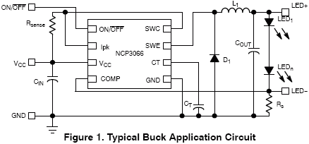
Der: I'm having issues getting my driver to work. It's the NCP3066 chip, in buck topology. I know yours is in boost, but I'm having issues. The driver isn't putting out enough current. I've followed the Excel Design Tool, input all my parameters, and the LEDs are barely lit. Do you have any suggestions?
 
PS + Arduino + CAT1401

PS + Arduino + CAT1401

Der: I have soldered my 3xCAT4101 board and tested it with a arduino (seeeduino). I can light and dim two cree XR-E's on a bell curve over about a 45sec cycle.

Next I would like to integrate my 24V PS with the arduino and the 3xCAT4101. Do I connect the Vin of the seeeduino directly to the 24V PS or do I provide a 5V (LM7805) voltage regulator? Or do I just power the seeeduino with a independent 5V PS while connecting the PWM to the CAT1401?

I noticed your pics of your setup a few pages back but I could not decipher what was really being done.
 
The CAT4101 has the following inputs in my 3-up design:

1) 24v: Connect to your LED's power supply (typically 24v for 6 LEDs)
2) 5v: Connect to any 5v supply. It's very low current. If you're using a 5v micro (your Seeeduino), connect to that device's 5v pin(s).
3) PWM: Self-explanatory.
4) GND: Connect to the GNDs of ALL the above devices (i.e. your 24v supply and the Seeeduino).

Typically, you'd have the Seeeduino fed from it's own power supply (usually a wall wart somewhere around 9 - 12v). 24v is out of it's input range so I wouldn't try to run it from that supply, unless you put a regulator between them and stepped voltage down.
 
Der: I'm having issues getting my driver to work. It's the NCP3066 chip, in buck topology. I know yours is in boost, but I'm having issues. The driver isn't putting out enough current. I've followed the Excel Design Tool, input all my parameters, and the LEDs are barely lit. Do you have any suggestions?

Check the Rsense and Rs values carefully. Either can limit current.

Also, make sure your chip is actually operating. i.e. check the whole design over. Make sure your timing cap is a suitable value. Make sure the chip is in the PCB in the correct orientation. Try with a different LED count and power supply voltage. etc.
 
In the design tool, if I change the desired current output, the values the excel sheet says I need to change are for the inductor. How would the inductor have dependancy on current output?
 
The size of the inductor affects stability and waveform of the output. Basically, the IC creates a square wave (on/off signal) and the inductor, diode, and other components "after" the chip basically turn that into a reasonably stable DC current.
 
The size of the inductor affects stability and waveform of the output. Basically, the IC creates a square wave (on/off signal) and the inductor, diode, and other components "after" the chip basically turn that into a reasonably stable DC current.

That's what I assumed too, but yet the design tool is stating that it's what sets the current. I don't get it. I also saw in the data sheets a simple formula for manually calculating the current, but can't figure out what one of the variables is. The equation is Vref/Rsense = Iled

I do not know what I would be using as the reference voltage. I'm guessing it's the voltage drop across the whole string of LEDs, but using that give a Rsense value of ~22 ohms. That just doesn't seem right.
 
The inductor does NOT set the current. The size (inductance) of the inductor with respect to the targeted current, voltage, etc. is important to make sure it functions correctly, but it's not involved in actually controlling or limiting the current. Inductors do have max current ratings, but that's more of a "do not exceed this value" kind of thing. For instance, if your peak current will be 900mA, you might want an inductor rated for 1A.

The current is basically set by Rsense and Rs. Rs is the current limit resistor, it "caps" the max current flowing through the IC. In normal operation, it shouldn't really come in to play. The important component is Rsense, which is the sense resistor. The IC measures the voltage drop across that resistor and modulates current to keep the voltage at a predetermined nominal value.
 
So I did some calculations, changed my Rsense to another value, and nothing. So, I'm guessing my inductor is wrong, but it's getting pretty frustrating
 
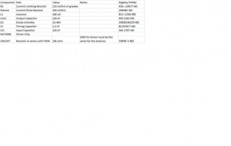
Can you post exact part values for everything you're using, and a schematic or photo of your circuit?

Edit - unless your inductor is WAY wrong, it really shouldn't cause the behavior you're describing. I'd look for a misplaced connection, something in backwards, etc.
 
I attached them since my photobucket doesn't seem to be working correctly at the moment. There is a little confusion on the diagram with Rs and Rsense though.

EDIT: would the diode installed backward cause this? That was the one part I wasn't really confident in
 

Attachments

  • ledtreiber_ncp3066.gif
    ledtreiber_ncp3066.gif
    7.6 KB · Views: 12
  • BOM.jpg
    BOM.jpg
    22.7 KB · Views: 12
The Rsense you have on that BOM is 294 ohm. You probably want more like .294 ohm, or something else in that range, depending on your desired current.

Nah, 294 mOhm. I like to keep things in mili's

EDIT: looked at my purchase orders...I in fact ordered the 294's and not the .294's....at least I know that's what's up.
 
Back
Top