You are using an out of date browser. It may not display this or other websites correctly.
You should upgrade or use an alternative browser.
You should upgrade or use an alternative browser.
DIY LED driver for reef lighting
- Thread starter der_wille_zur_macht
- Start date
Have you found the answer to this question?What is the voltage drop of the string of LEDs at 700 ma?
imagex
New member
I don't understand a bridge at B. You would use the PWM for dimming.
I htnk a lot of theunknonw parts ar capacitor for stabilizing the voltage. Sorry not real familiar with the 3 board version.
1) llok like a cap on the 5 volts.
3) I am guessing this is a 24 volt cap.
2) thius is the sense resirotr should go to ground.
ghellin - thre resitor depends on the board it has to match the board layout. There is ahcart in the datahseet that tells ohm for a varietyof currents.
hey this is the stevesled driver to the tee.. thats what i was asking a while back about how he's using all the cat4101's on one dimming source... i asked if it was possible before and everyone decided against it.. i think including you.. If i'm not mistaken that design is the exact steve's led driver i had here..
TheFishMan65
New member
Boy I had a bad typing day. The CATs don't draw much current for the PWM. They have a 200k ohm resistor. So 5 volts / 200k = .025 milliamps. IIRC the arduino supply 40-50 milliamps. So an Arduino pin could drive 1600 of these.
I don't ever recall saying you can't hook up multiple dimming signals to one source. IMHO most dimming source will be capable of driving multiple driver, but check the current to be sure.
I don't ever recall saying you can't hook up multiple dimming signals to one source. IMHO most dimming source will be capable of driving multiple driver, but check the current to be sure.
TheFishMan65
New member
Depends on the power supply. I have a 20 amp (maybe 13) that would do it (or maybe 2). There is a 6.5 that was popular (I hear no longer available) that would take 3 to make it work. I sort of recommend 2 supplies one for white and one for blue so you can adjust the voltage for optimum efficiency for each color.
I have been following this thread for some time now and want to thank you all for your efforts. I ordered some CAT4101s but am yet to order LEDs. I had decided to order cree XP-Gs but now the cree XM-Ls seem tempting... There is a mention in the CAT4101 datasheet that they can be run in parallel to run a LED string with more than 1 Amp. Would it mean just connecting the led pin of 2 CAT4101s together. What happens to the PWM? should the same signal be applied to both CAT4101s? I have some 1W /350 ma leds to experiment on. Was thinking of supplying 150 ma each through 2 CATs to see if a total of 300 ma is output. Please let me know your thoughts.
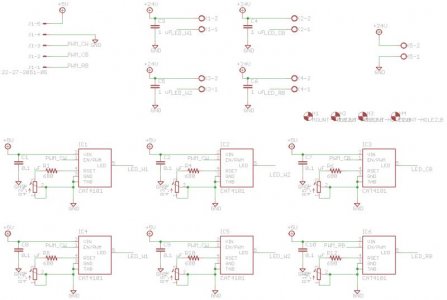
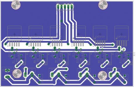
With reference to my post above, I have tested the CAT4101 driver as I described and it works. I have made the schema to drive 2 XM-L led strings with 2 CATs in parallel and 1 string of blue and 1 of royal blue XP-Es. Please let me know what you think about it.
Attachments
Last edited:
TheFishMan65
New member
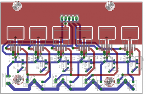
Looks like 5 volts is coming in with the PWM signals? IMHO:
- I would move the connector for PWM further away for heat reasons.
- Also (may not be showing) you are missing the vias around the CATs for heat dissipation.
- For the same reason I would extend the ground plane down and add one on the back side (once again may not be shown).
- Beef up the ground. PIN3 IIRC is ground, but the time it gets back to the connector it could have 6 amps going through it. I believe the current width would melt.
- If you want to make it more general purpose don't connect the LED together on the board. Then if later you decide to drive 6 strings of XPs you could.
Looks like you are doing the same thing I did with a dimming pot. I can't read the schematic to well what is your default resistor and pot.
Really appreciate you quick reply, Fishman.
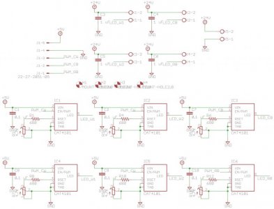
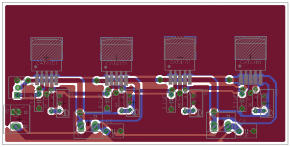
- I have moved the PWM connections a little further away. The PWM and +5v are together because I will be using a atmega32 to drive the PWM and will take +5v from the same board. I will also solder a heat sink on the top layer. BTW, there is a GND from 24V supply also.
- As for the vias, I am planning to DIY 2 boards like this and will drill the vias manually after etching and put some solid copper wires through the holes.
- Sorry, I missed the ground plane. I have added it now.
- Actually, this will not be general purpose. Each board will drive 2 string of 7 Cree XM-Ls, one string of 6 cool blue XP-Es and 1 string of 6 royal blue XP-Es. 7 XM-Ls at 1500ma will be 21.7 V and 6 XP-Es at 750ma will be 21.0 V. So, 2 CATs will require to burn 0.7V extra at 750ma. Hopefully, this will not be a big issue.
Initially, I'll drive all the CATs at 750ma and then take it from there. The resistors are 680 ohms but I think I'll put a 560 ohms instead. The pots are 4.7k with multi-turn and have really fine control.
Have already ordered LEDs from Cutter. Will start a build thread as soon as I get them.
Attachments
Last edited:
TheFishMan65
New member
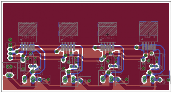
I don't like the bottom later the center two CATs have too many traces under them IMHO for heat dissipation. I am no expert on board, but here are some more pennies ") . Make the board wider if you can and spread the CATs out. If forgot how many square inches they say. You might also want to consider a heat sink (I had to do that) or at least don't exclude one in the way you design.
. Make the board wider if you can and spread the CATs out. If forgot how many square inches they say. You might also want to consider a heat sink (I had to do that) or at least don't exclude one in the way you design.
I am not sure how well your copper wire theory will work. Most likely they won't be flush so the back of the CAT may not make good thermal contact. Have you considered one of the existing boards and just tying the output of 2 CATs together.
. Make the board wider if you can and spread the CATs out. If forgot how many square inches they say. You might also want to consider a heat sink (I had to do that) or at least don't exclude one in the way you design.I am not sure how well your copper wire theory will work. Most likely they won't be flush so the back of the CAT may not make good thermal contact. Have you considered one of the existing boards and just tying the output of 2 CATs together.
vincent843
New member
The PWM and +5v are together because I will be using a atmega32 to drive the PWM
Dummy here, how does it work?
Dummy here, how does it work?
TheFishMan65
New member
The Atmega has a 5 volt regulator on board so rather than repeat the circuitry he is just getting the 5 volts from the Atmega.
I don't like the bottom later the center two CATs have too many traces under them IMHO for heat dissipation. I am no expert on board, but here are some more pennies
I am not sure how well your copper wire theory will work. Most likely they won't be flush so the back of the CAT may not make good thermal contact. Have you considered one of the existing boards and just tying the output of 2 CATs together.
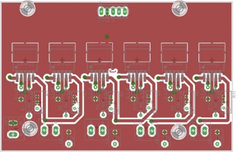
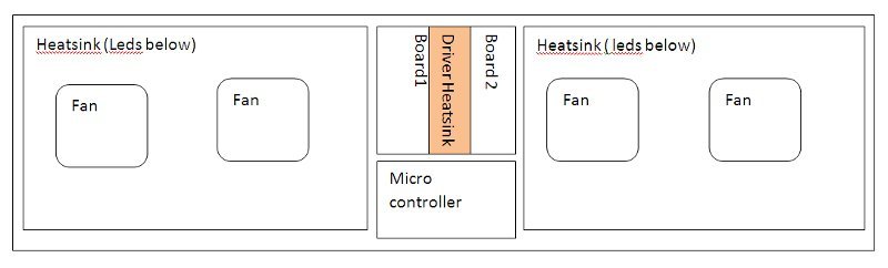
Fishman, there are certain constrains I have to work with. I have a aluminium sheet on which I am putting heatsinks( the heatsinks have very low fins). I have attached the layout. Now the 2 CAT boards will be mirrored and a common heatsink will join them. So given I have active cooling fans controlled by the microprocessor, do I really need the vias below the CATs?
There is one more way in which I can broaden the boards and stack them one over the other... will the cooling be better this way?
Unfortunately I have to do this DIY as getting just 2 custom boards made will cost me a lot here.
The PWM and +5v are together because I will be using a atmega32 to drive the PWM
Dummy here, how does it work?
Vincent, the Atmega32 microprocessor works on +5v. I will have 2 separate power supplies, a 24V 13A for LEDs and a 12v 3A for the microprocessor and Fans. The 5V for the CATs will come from the microprocessor board along with PWM signals.
Attachments
Last edited:
TheFishMan65
New member
I don't know for sure, but it sound like you are doing LED-> aluminum sheet->heat sink. This is not recommened since it means the heat goes through to layers of thermal glue/grease which never works as well as it should. So if possible do LED->Heat sink.
The CATs do not have a fan blowing on them so I would not consider them active cooling. And I don't know if just the heat sink, vias, or both is enough.
I would avoid stacking.
Somewhere early on IIRC there was another guy from India P????. You might try PMing him I think he found a place to build them for him.
I don't mean to sound negative. I will point out as many faults and issues as I can find (and I may be wrong about some of them). You will change whatever you think makes sense (don't change the ones I got wrong). Then you will build it and it will work beautifully. Well at least until something goes wrong, and then we will try and help you fix it.
Or to put it short.
Build what you think will work and let us know the problems (if any) and we will try and help fix them.
I don't mean to sound negative. I will point out as many faults and issues as I can find (and I may be wrong about some of them). You will change whatever you think makes sense (don't change the ones I got wrong). Then you will build it and it will work beautifully. Well at least until something goes wrong, and then we will try and help you fix it.
Doesn't sound negative at all! You have at least one LED build under your belt and I am just taking advantage of your experience.
")
Guess it's back to the drawing board then... Thanks a lot for the pointers!
Regarding the aluminium sheet, I was planning to have a 10mm thick sheet with leds and heatsink screwed on to it with thermal paste in between. Heatsinks available here are 30(l)x5(w)x2(h) cms. I thought this was not adequate by itself.
TheFishMan65
New member
Just to confirm 11.8x2x0.8 inches. That should be fine IMHO and if you can get air flow between them fans may not be needed. You can probably get 6 LEDs on that. I am using smaller ones than that (13.8x1.x0.3 inches) with 6 LEDs.
vincent843
New member
the Atmega32 microprocessor works on +5v. I will have 2 separate power supplies, a 24V 13A for LEDs and a 12v 3A for the microprocessor and Fans. The 5V for the CATs will come from the microprocessor board along with PWM signals.
I must asleep when first read your post. For some reason I read tied toghether....
I must asleep when first read your post. For some reason I read tied toghether....
TheFishMan65
New member
You probably want to add mounting holes. Other than that I think they should work. You might consider making all "blue" boards then typing the appropriate lines together. I don't know your experience in making PCB (I did once), and you may be better of making 5 the same and picking the best 3.
You probably want to add mounting holes. Other than that I think they should work. You might consider making all "blue" boards then typing the appropriate lines together. I don't know your experience in making PCB (I did once), and you may be better of making 5 the same and picking the best 3.
Oops! forgot the mounting holes. Yes, I have made a few PCBs for microprocessors, so I think I can handle. Thanks a ton for your help!
Similar threads
- Replies
- 0
- Views
- 88
- Replies
- 6
- Views
- 851
- Replies
- 20
- Views
- 2K