DIY LED driver for reef lighting

slobodan, I think we have hijacked enough. Why don't you start a new thread and post a link in this one for those (like me) that want to follow. I think the next step is a picture of ho you want to space the LEDs with row and column disignator so you can describe which LEDs come on when. I am lost on hat I think you want, but I am sure the brain power of RC can help you find ananswer.
 
Good idea fishman.. I apologize, didn't mean to hijack.. I'll start new tread but it might take week or so since I'm due for surgery tomorrow.

I'm eagerly waiting for terahz findings on his driver..
 
Apparently the folks are Steve's LEDs use the CAT4101 (another RC said they got a board). Apparently they dim all channels at one time. They do this by using a sense resistor for each CAT (they sell a 4 board version) and then feed all those signals through a common potentiometer and then to ground. Not only this apparently the pot is a panel mount variety and goes to a connector on the board - nice kelvin connection :). I had thought of doing something like this, but worried about interference from one CAT to another. So any design comments?
So in trying to get an answer to shared CAT4101 analog dimming I sent:
I would like to design a board with several CATs on it, but a common current control. Can Rsense be replaced with a potentiometer and then fed to all the CATs. Or perhaps a unique Rsense for each CAT and then a common potentiometer.
to OnSemi, they avoided the question
It is better (more accurate) to have one potentiometer per driver.
I guess I will try again :)
 
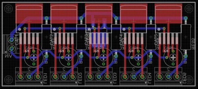
Working on a PCB for my drivers with Eagle at the moment. It will house 5 Cat4101s, 6 sets of screw terminals (1 for each string, plus input voltage) 6 surface mount caps, an ldo, 5 5W resistors and 5 trimmer pots. Assuming my understanding is right that is all the board should need to be fully functional. I may be wasting space (though they don't really make the board much bigger with my current layout) keeping the big resistors on it as well, i thought it would be nice to have them on something secure and right next to the adjustment pot. As is the board measures 3"x1.75" i think.

The real question is though, how do i do the wires on the board in Eagle properly? If i use the signal thingy it seems to make all the wires as small as the limit is, and then changing them only changes 1 section at a time. Or do i use the route thingy and pick my own sizes? What size wire should i use for a trace that might pass 5A? Or 3.5A or 1A?

I'll get some pics of the plan later (hopefully with some proper wiring).
 
A few points to think about:
- I think you left off the 5 volt regulator. Or is that Ido???
- Make sure you leave plenty of room around the CATs for heat dissipation
- Place the resistors between +24 and the terminal. Not the terminal and the pin on the CAT. Why? If you do it the first way you can attach the voltmeter to +24 and never move that connection as you measure all the circuits. The second way will require moving both leads of the meter.
- Another space saver switch to .1 ohm half watt. Means that the volts shown must be ultiplied by ten. Also gain a little in efficiency.

I hope this help, and sorry I don't use eagle enough to help.
 
Yeah the LDO is a 5V regulator. Even though i will run it off a controller which could put out 5V, i figured its better to have it from the PSU since i have extra power anyway.

I don't know how much heat these things would generate nor do i really know much about heat dissipation in a board, but i have about 1/8" between each chip and as much ground plane as i can for the heat to soak into. I have all the chips on the same side, along the same edge (makes it neater/easier to hook up) but i suppose for heat reasons that might be bad.

I hadn't even thought of that for the resistors, but it is handy to remember for testing later. Even so, i had the resistors as you mention, before the string, mainly to make the wiring of the board simpler, but apparently it had other good effects.

Would the smaller resistor make it less accurate to measure? Or would it depend on what you use to measure it mainly? If its not then i will probably go with that, since i don't have most of the parts anyway and the resistors are the biggest components on the board.

Back to designing the board then.
 
So, as I suspected C4 connecting the Vadj pin to ground was messing up with the PWM. After disconnecting the pin, PWM worked like a charm:

<object width="400" height="225"> <param name="allowfullscreen" value="true" /> <param name="allowscriptaccess" value="always" /> <param name="movie" value="http://vimeo.com/moogaloop.swf?clip_id=27844464&server=vimeo.com&show_title=1&show_byline=1&show_portrait=0&color=&fullscreen=1" /> ******* src="http://vimeo.com/moogaloop.swf?clip_id=27844464&server=vimeo.com&show_title=1&show_byline=1&show_portrait=0&color=&fullscreen=1" type="application/x-shockwave-flash" allowfullscreen="true" allowscriptaccess="always" width="400" height="225"></embed></object>

So I just need to rewire the jumpers on the board to disconnect right before the Vadj and add the pot and the board should be ready.


Terahz, where are you using/sourcing for the 48v power supply?

I use a bench PSU for the testing, but after I'm done, I plan to wire the two 24V potrans PSUs I have for the CATs.
 
Used manual route to run my wires, sized the Vin at .050 and the rest at 0.032. Board measures 1.325" x 3.050." I didn't take a pic with the ground fills since it wouldn't show much at that point....

I'm sure there is an electrical engineer who would go ape over how i wired it, but i have not done this before =D. I just am obsessive enough to have to have it as neat as this (the autoroute drove me crazy)....

In case someone is curious:
VIN 1: GND
VIN 2: +24V
LED# 1: - LED
LED# 2: + LED
LED# 3: PWM
 

Attachments

  • board.jpg
    board.jpg
    74.5 KB · Views: 3
IMHO, it needs a little more work.

- IIRC you need almost 2 square inches of board for each CAT.
- Packing a resistor that will give off heat between CATs is only asking for trouble
- Did the not show or are there any vias under the CATs
- You need a wider trace for 24 volts, parts of it maybe supplying 5 amps
- same for ground, but depending on how you did the ground plane maybe covered.
- Is the LDO under the middle CAT? Both these parts will get warm if not hot.
 
The resistors are on the reverse side, not that it would matter much i suppose.
There is a via under each cat, for the 5V line. Between the ground tab and the pins.
I'll look into the trace width stuff, as i mentioned i have no idea how wide it needs to be.
The ground is pretty much covered i think, everything left on the board is ground after i put the planes in.
The LDO is indeed under the middle cat, with its ground tab right around where the pins of the cat are.

Really i was mostly thinking that i would bolt the board to the heat sinks of my LEDs. I don't know if the 4 points contact would transfer heat effectively enough though. Or for that matter if the LEDs heat sink will be hotter than the board...
 
I think you need to reread the datasheet (It has been a while since i looked at it), but there used to be a layout picture. The CAT needs ground planes connected by vias (15-25) for good thermal transfer. If you can't find it I will dig back in.

IIRC DWZM fit as many as he could (3) in the limited size the eagle layout progtam allowed.
 
Ah i skipped over that in the datasheet (its one of the many i have open all the time until i get this done). That shouldn't be too hard to incorporate, though now placing the LDO there is impossible. No big deal. Also found some recommended trace sizing, essentially meaning my trace for the high amp lines is 1/3 the size it should be (.150). It also seems like i could have made the schematic in eagle and had it calculate the size of the traces or something? I didn't bother making a schematic, i guess i know what i will do tonight.

But i think i may have a solution for the general problem i have. I have been basing the design on minimum square inches for price reasons (as is it would cost $10 each board plus $10 handling and i need 2 boards) but i have found what could be a better solution. This one site offers 10 boards of 10cmx5cm for $25. Or 10 boards of 5cmx5cm for $10. I could do multiple drivers (still not 5 i guess?) on the ~2"x4" board (bigger than my current design) or a single one each on the ~2"x2" one and either way come out better off...
 
Field Report 2:
So the first mistake I found was that my Rsns (R1) was 0.1 Ohms instead of 0.22Ohms. Good thing I had a few extra, so I added another resistor there (making a small tee pee in the process :) ). Then the Vadj pin was supposed to be powered by an internal source to 1.24V, but I suspect that my voltage divider messed that up because it was measuring ~0.15V which would explain the low current. So I decided to proceed with analog dimming, which would set the voltage properly on that pin.

So I set the jumpers for analog dining, wire a 5V power source to the ADJ pin and hit the power button. Next thing I know, I'm blinded...
LM3409_analog_working.jpg

(That string is 3 RB, 3 CW and the rest NWs).
I look at the multimeter to see the current: 860mA! Hooray! I quickly remove the second Rsns resistor to the previous 0.1 Ohms, just to see what happens: 2A :D.

For PWM, I'm thinking that until the Vadj pin is completely disconnected, the max current will be set to something very low so PWM will work only on that current.

BTW now that I know these work, I have a few extra boards if anyone is interested, send me a PM. I'll test PWM later today and make fixes to the design, than I'll post the eagle files and BOM.

THz

How you coming with the eagle files an BoM?
 
I use a bench PSU for the testing, but after I'm done, I plan to wire the two 24V potrans PSUs I have for the CATs.

Was looking on Ebay and you can get 48v 7.2 amp power supplys for about $45.00. Some appear to be MeanWell knockoffs.
 
Ok, so I made a few tiny changes to the board and I think it is good to go. I decided not to add a pot in the end, since a pot is kind of useless on the board. I figured a pot can be wired easily to be mounted on a box.

For PWM: don't populate R4, R6, R7 and C4 and jumper the middle 2 pins on the jumper header.

For Analog: populate everything, and jumper pin 1 with 2, and 3 with 4.

The bom has values of R6 and R7 for 5V input. If you have another input, please calculate the appropriate voltage divider values. Also in the BOM are values for 12 XPG leds at about 1A. I can't tell how accurate they will be for that 1A, but should be close. Refer to the lm3409 data sheet to get the formulae for calculating the appropriate Rsns (R1) and L1 values. That's what basically determines your current. For lower current, you need higher resistance Rsns (so for 350mA something like 0.44Ohm, for 500mA ~ 0.34Ohm, for 750mA ~ 0.25Ohm etc.) but what exactly, would depend on the ripple of the inductor (L1).

BOM and Eagle files of v0.3 can be found here:
http://joro.geodar.com/code/LM3409HV0.3.zip

P.S. to remove the thermals: change -> thermals -> off; then click on the (ripped up) planes you don't want thermal relief on.

Enjoy.
 
Back
Top