- Forum
- More Forums
- Reef Club Forums
- SouthWest Region-Reef Club Forums
- Arizona - Fish & Reef Aquarium Group (FRAG)
You are using an out of date browser. It may not display this or other websites correctly.
You should upgrade or use an alternative browser.
You should upgrade or use an alternative browser.
DIY LED Lights
- Thread starter kjonulak
- Start date
kjonulak
New member
Awesome project! Looking forward to seeing the finished setups.
Thanks! I'm working hard to get 2 of these lights up and running this weekend.
If anyone would like to come by, I would be happy to show you my lights and the progress on these lights.
kjonulak
New member
Great job Ken, you look like your having fun
Thanks Mike. I do enjoy the challenge of designing and building LED lights. I'm always learning something new that I can apply to this technology.
kjonulak
New member
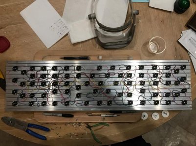
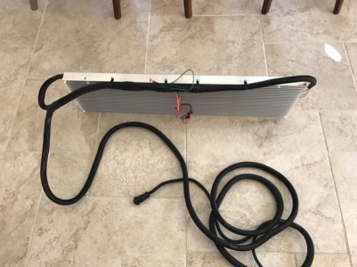
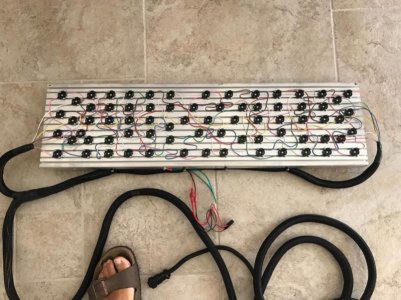
So the wiring from LED to LED is completed on 2 out of the 4 heatsinks.
One thing to note, is that LED's can and do get hot. The number one enemy of an LED is heat. The hotter they get, the quicker they will burn out. Believe me, I've burned out a few. To keep the LED's from getting too hot, you need a heatsink. Just as the name implies, the purpose of a heatsink is to absorb heat. The fins on the opposite side of the heatsink are there to dissipate the heat into the air. Now from what I read, it is best to keep the temperature of a heatsink at or below 125 degrees. Me, I like to keep the temperature down around 100 degrees. I will be using 2 Gelid 120mm fans on each of the heatsinks to remove as much heat as possible. The fans that I use also have a thermal probe that will vary the speed of the fan. So the cooler the heatsink, the slower the fan spins. As the heatsink heats up, the fans will spin faster. In the past I have also temperature switches that would measure the temperature of the heatsink and turn the fans on and off based on temperature.
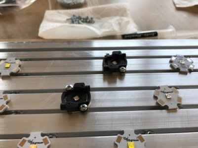
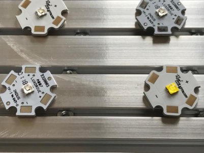
The LED's are mounted to an aluminum plate typically called a star package. The metal plate helps to pull the heat from the LED. The metal plate or star package needs to transfer it's heat to the heatsink. The base of the star package is not perfectly flat. In order to help transfer the heat from the star package to the heatsink a thermal compound is used to aid in the heat transfer.
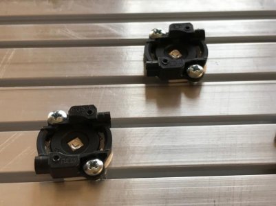
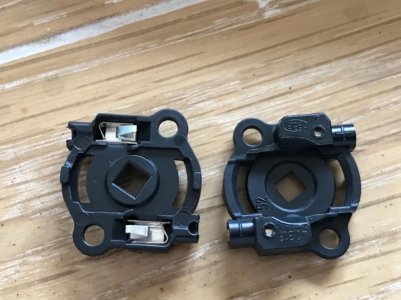
So the thermal compound goes between the bottom of the star package and the heatsink. To compress and hold the LED/star package to the heatsink I use a product called a BJB Solderless LED Connector. The connector has 2 metal tabs on the underside that press against a set of flat metal connectors on the top side of the star package. The connectors are listed as + and - and the BJB connector as a set of + and - indicators where the wires will be inserted. It is important that the polarity of the LED's and connectors all match.
As for the wire that I use to connect all the LED's together, the BJB connectors can use either an 18 or 20 gauge solid core wire. The perfect wire for this is the same wire used for wiring sprinkler system zone valves to the sprinkler controller. I had a bunch of this wire left over from when I installed my drip system in my new house. Plus all the individual wires are colored coded which is also perfect for connecting the LED's. I will typically use the color wire for the LED type that I am connecting together. So for example white wire to connect the white LED's, purple wire for the UV LED's, etc. The only time I vary this is for my Royal Blue/Blue LED's. Since I have the 2 parallel Royal Blue/Blue series LED's for 1 of the 2 series circuits I will use a blue wire. For the 2nd Royal Blue/Blue LED circuit, I'll use another color, this time I used brown. It makes it easier to see each of the 2 parallel LED circuits.
Tomorrow I will work on getting the cables that run from the heatsinks to the power box/modules built. Then I will test each of the individual power supplies within each of the power box/modules and I will test the LED circuits prior to connecting power and turning them on. If all goes well, I hope to have these 2 sets of lights turned on this weekend. Then I can start working and the last 2 sets of lights.
One thing to note, is that LED's can and do get hot. The number one enemy of an LED is heat. The hotter they get, the quicker they will burn out. Believe me, I've burned out a few. To keep the LED's from getting too hot, you need a heatsink. Just as the name implies, the purpose of a heatsink is to absorb heat. The fins on the opposite side of the heatsink are there to dissipate the heat into the air. Now from what I read, it is best to keep the temperature of a heatsink at or below 125 degrees. Me, I like to keep the temperature down around 100 degrees. I will be using 2 Gelid 120mm fans on each of the heatsinks to remove as much heat as possible. The fans that I use also have a thermal probe that will vary the speed of the fan. So the cooler the heatsink, the slower the fan spins. As the heatsink heats up, the fans will spin faster. In the past I have also temperature switches that would measure the temperature of the heatsink and turn the fans on and off based on temperature.
The LED's are mounted to an aluminum plate typically called a star package. The metal plate helps to pull the heat from the LED. The metal plate or star package needs to transfer it's heat to the heatsink. The base of the star package is not perfectly flat. In order to help transfer the heat from the star package to the heatsink a thermal compound is used to aid in the heat transfer.
So the thermal compound goes between the bottom of the star package and the heatsink. To compress and hold the LED/star package to the heatsink I use a product called a BJB Solderless LED Connector. The connector has 2 metal tabs on the underside that press against a set of flat metal connectors on the top side of the star package. The connectors are listed as + and - and the BJB connector as a set of + and - indicators where the wires will be inserted. It is important that the polarity of the LED's and connectors all match.
As for the wire that I use to connect all the LED's together, the BJB connectors can use either an 18 or 20 gauge solid core wire. The perfect wire for this is the same wire used for wiring sprinkler system zone valves to the sprinkler controller. I had a bunch of this wire left over from when I installed my drip system in my new house. Plus all the individual wires are colored coded which is also perfect for connecting the LED's. I will typically use the color wire for the LED type that I am connecting together. So for example white wire to connect the white LED's, purple wire for the UV LED's, etc. The only time I vary this is for my Royal Blue/Blue LED's. Since I have the 2 parallel Royal Blue/Blue series LED's for 1 of the 2 series circuits I will use a blue wire. For the 2nd Royal Blue/Blue LED circuit, I'll use another color, this time I used brown. It makes it easier to see each of the 2 parallel LED circuits.
Tomorrow I will work on getting the cables that run from the heatsinks to the power box/modules built. Then I will test each of the individual power supplies within each of the power box/modules and I will test the LED circuits prior to connecting power and turning them on. If all goes well, I hope to have these 2 sets of lights turned on this weekend. Then I can start working and the last 2 sets of lights.
Attachments
Sisterlimonpot
Premium Member
This DIY is right up my alley! I have a bunch of meanwell drivers and CREE LED's sitting in a box somewhere in my garage. Never got around to doing anything with them. At the moment, I don't have any plans for them. But it's good to hold onto them until a need arises.
kjonulak
New member
This DIY is right up my alley! I have a bunch of meanwell drivers and CREE LED's sitting in a box somewhere in my garage. Never got around to doing anything with them. At the moment, I don't have any plans for them. But it's good to hold onto them until a need arises.
Jimmy, if you need some heatsinks let me know I have extras.
kjonulak
New member
As fate would have it, I ran short on wires for my cables this past weekend. So I’m waiting for amazon to ship me some more. In the meantime I am working on getting the ends on the cables I do have plus I have 2 more heatsinks that need LED’s added to them. So no rest for the weary. Once the additional wires arrive I will finish up the cables.
kjonulak
New member
Let There Be LED Light!
Let There Be LED Light!
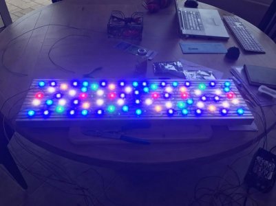
So finally yesterday I turned on one of the LED lights. :dance:
At this point I have the following components all finished:
The UV, Blue and Cool White Power Module/Boxes (4)
The Warm White, Red and Green Power Module/Boxes (4)
Heatsinks with LED's attached (2)
Cable assemblies (4)
I still need to finish adding the LED's to 2 of the heatsinks and connect them and the one completed heatsink/LED's to the power module/boxes.
During my testing I found on one of the cable assemblies the Cool White connections weren't working just right. I was getting some weird readings when I was testing the cable with the power module/boxes, so I cut off the connectors and added new ones and that seems to have fixed it.
When I turned on the one LED light assembly and was testing the dimming circuitry, which is also working, I noticed that the red led circuit required about 30% power to turn on. This indicates to me that I am below the minimum voltage needed to get to the constant current level of the supply. This is the first time I am working with the photo red led's so my estimate of 3.3Vdc is most likely too high for these led's. So I have one of two ways to fix this. Change out the power supply for one with a lower voltage or add more red led's. It will be easier for me to add one or two more red led's vs changing the supply.
Now one other issue if you want to call it that with the LPF power supplies is that when you get really low when dimming, the LED's will blink. This is because you are well below the minimum threshold for the constant current range of the power supplies. So depending on the dimming control unit you are using you can either have the dimmer stop at a point right before the blinking starts and the LED's will always stay on just a little or you can put a timer on the power supplies that turns off the power to them at night. I will most likely just add a timer.
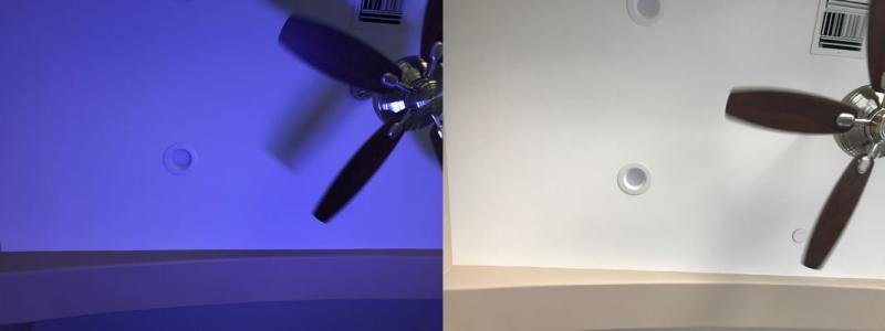
With the pictures it is hard to see how the LED's are going to perform when they are just sitting on a table, especially when it is during the day. The one picture shows what the color looks like on my ceiling. The ceiling is 10' high and the LED's are on my kitchen table, so the distance between the two is about 7' away. I like the color, plus it is also during the day and I am getting outside light coming in.
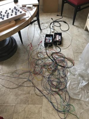
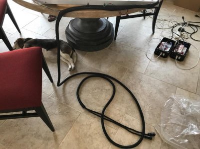
What a mess of wires coming from the power module/boxes to the LED's. The cable sheathing I picked up does a great job of tiding up that mess.
Let There Be LED Light!
So finally yesterday I turned on one of the LED lights. :dance:
At this point I have the following components all finished:
The UV, Blue and Cool White Power Module/Boxes (4)
The Warm White, Red and Green Power Module/Boxes (4)
Heatsinks with LED's attached (2)
Cable assemblies (4)
I still need to finish adding the LED's to 2 of the heatsinks and connect them and the one completed heatsink/LED's to the power module/boxes.
During my testing I found on one of the cable assemblies the Cool White connections weren't working just right. I was getting some weird readings when I was testing the cable with the power module/boxes, so I cut off the connectors and added new ones and that seems to have fixed it.
When I turned on the one LED light assembly and was testing the dimming circuitry, which is also working, I noticed that the red led circuit required about 30% power to turn on. This indicates to me that I am below the minimum voltage needed to get to the constant current level of the supply. This is the first time I am working with the photo red led's so my estimate of 3.3Vdc is most likely too high for these led's. So I have one of two ways to fix this. Change out the power supply for one with a lower voltage or add more red led's. It will be easier for me to add one or two more red led's vs changing the supply.
Now one other issue if you want to call it that with the LPF power supplies is that when you get really low when dimming, the LED's will blink. This is because you are well below the minimum threshold for the constant current range of the power supplies. So depending on the dimming control unit you are using you can either have the dimmer stop at a point right before the blinking starts and the LED's will always stay on just a little or you can put a timer on the power supplies that turns off the power to them at night. I will most likely just add a timer.
With the pictures it is hard to see how the LED's are going to perform when they are just sitting on a table, especially when it is during the day. The one picture shows what the color looks like on my ceiling. The ceiling is 10' high and the LED's are on my kitchen table, so the distance between the two is about 7' away. I like the color, plus it is also during the day and I am getting outside light coming in.
What a mess of wires coming from the power module/boxes to the LED's. The cable sheathing I picked up does a great job of tiding up that mess.
Attachments
kjonulak
New member
Any progress with plumber?
Nope. Any luck on your end?
I did get a message from him which indicated that if he doesn't get the tanks installed in August, it could be while. He is going on vacation in September. Not good news.
kjonulak
New member
LED's Almost Ready
LED's Almost Ready
So all 4 LED's are working. I have all the wires bundled up. I just need to add the fans and lenses on the LED's. I will be mounting them above where my tank is going to be this week.
I did have a couple of issues.
I found a bad BJB LED connector. I had a spare, so I swapped it out.
I did notice that the Red LED's would blink if I lowered the power level below 30%. This was fixed by adding another LED (I used Royal Blue) to the 6 Red LED's. Adding one additional LED was enough load on the power supply to now let me lower the power level to 0% before the LED's started to blink. The power supplies I am using cannot go to 0% so at the low end there is a slight blink. When the lights are over the tank you will not see the blinking. What I will be doing is putting the power supplies on a timer. Once I get to the time at night when the lights will be off, I will turn off the power to the power supplies.
The second issue is a bigger one. The Bluefish controller I am using works just fine with one light. When I plug a 2nd light into the controller, some of the lights will stay turned on. I can not get them to turn off. I have an email out to the person/company that makes the controller to see if there is a solution. I checked my wiring a couple of times, but I am going to check it again just to make sure I didn't wire something wrong. The only solution I can see at this point is that I will need one Bluefish controller per light ouch. I was not expecting to need that. I've used other controllers in the past that could handle multiple power supplies connected to the same dimming output. Hopefully the person that makes the Bluefish controller will get back to me soon.
Also after 6 years, the LED light over my 45 gallon cube dropped the blue colors this weekend. So I did some troubleshooting and found that the power supply for the blue LED's was bad. I had a spare and swapped it out. It took me about an hour to troubleshoot the issue and to swap out the bad supply.
Attachments
kjonulak
New member
Bluefish Controller Update
Bluefish Controller Update
I spoke with the designer/builder of the Bluefish controller yesterday. He indicated that the MeanWell LPF supplies only draw 0.1ma on the dimming circuit. The Bluefish controller is capable of supplying 40ma per channel. Theoretically that means I could have 400 LPF supplies on each channel. So the issue has to be on my end with the wiring. I am going to start from the beginning and rebuild the dimming distribution circuit for each channel and then add on each light one at a time to get the dimming to work correctly. I will post my findings.
Getting closer.
Also my 130 gallon tank will be installed tomorrow. This tank will be using 1 - Gen 3 Radion and 2 - Gen 4 Radions.
Then on to the 250 gallon tank. This is the one with my DIY lights.
What do you see is the primary difference between the Radion and your DIY?
I mean why didn't you do DIY over the 130 also? And the following question is also why did you decide to go with DIY instead of Radion?
kjonulak
New member
What do you see is the primary difference between the Radion and your DIY?
I mean why didn't you do DIY over the 130 also? And the following question is also why did you decide to go with DIY instead of Radion?
My main tank (250) will have a canopy over the top. The company I use to get blank fixtures from stopped selling them. So for the build over the 250 gallon you will not see the working part of the LED lights (heatsink, LED's, fans and wiring) so it doesn't need to look pretty. If I was to purchase lights for the 250, I would have gone with the Mitras LX-7, most likely 4 of them.
On the smaller tank (130) it is rimless with no canopy. I wanted a light that would function for what I want in the tank and look nice.
My preference would have been to build the lights over the 130 gallon also, but the need to have something that looks nice was the overriding factor.
I have a couple of Gen3 Radions that I picked up used. They seem to work. I was able to pick up a couple of used Gen4 Radions (not pro). I am going to use one of the Gen3's in the middle and the 2 Gen4's on either side of it and suspend them from my ceiling above the tank. The tank is 60" long so the Gen3 will be in the middle (30") and the Gen4's at 15" off center.
For my DIY build and can pretty much build it the way I want with the colors and number of LED's to get full coverage over the tank without having the shadowing issue that comes with LED's.
At the moment, I am very disappointed in the light controller. The dimming wiring I setup is correct. What I have found out is that if I hook up 1 light everything works great. When I hook up a 2nd or 3rd (haven't tried 4 yet) I can not get the LED's to dim down to an off level. If I measure the 0-10Vdc signal from the controller with one light I can get to the 0Vdc level (measured on my voltmeter). Which corresponds to the 0% level in the app. At the 1% level the LED's will flicker or blink, but they are so dim it really doesn't matter. When I hook up the 2nd light, I can't get the controller to go to 0Vdc. It stops at 0.58Vdc which is still high enough to keep the LED's lit. I can increase to the 10Vdc and I am still getting a smooth transition. With 3 lights connected the OVdc only goes to 0.68Vdc which is higher which means the LED's are still on.
The builder of the controller has been responding to my emails, but it takes a long time. He is not sure why it is happening. He built the thing, you would think he would know or offer to setup a test circuit and see what may be happening.
I also reached out to MeanWell and they actually called me today. I sent them my schematics and we talked at length as to what is happening. Maybe they can provide a solution. I'm thinking I have a grounding issue with the DIM- signal on the the dimming circuit with the MeanWell supplies. When I measure the ground circuit with the controller in place with no power applied, it all looks good.
Since one light works with one controller, my option may be to purchase another 3 controllers and the stereo to RJ45 cables. I will have to rewire the dimming wires in my power modules. It's doable, but also a very expensive fix to have to get another 3 controllers and wires.
Sisterlimonpot
Premium Member
Have they been able to rule out whether or not each string of LED's has to have very similar forward voltage?
Not sure how the drivers are constructed, however even when running 2 strings parallel to each other and then try to dim them via PWM one string will always start to flicker at the lower voltages while the other dims out correctly. not sure if that is something to look into or not but it might be something to entertain and rule out.
Hopefully (as you stated) you don't need to have a controller per each string...
kjonulak
New member
Have they been able to rule out whether or not each string of LED's has to have very similar forward voltage?
Not sure how the drivers are constructed, however even when running 2 strings parallel to each other and then try to dim them via PWM one string will always start to flicker at the lower voltages while the other dims out correctly. not sure if that is something to look into or not but it might be something to entertain and rule out.
Hopefully (as you stated) you don't need to have a controller per each string...
Each string is designed based on the power supply output. I always try to put as many LED's per supply based on the output voltage. The higher the load, the more smooth the transition is during dimming whether up or down. MeanWell has some good technical/design documents. Each LED string for the given color is the same on all 4 lights. So for example the UV setup for each light is 1 - LPF-25D-36 power supply with 10 UV LED's. So for the channel on the controller that is controlling the UV LED's all 4 strings are identical.
I have been running 2 parallel strings of blues for years now. I don't get any flicker regardless of the power level except at the 1% or below (LPF supply) which is fine. I have used different supplies (ELN series) which can go to 0 and turn off with no flicker. Both parallel circuits increase and decrease with no noticeable difference. I have used both 0-10Vdc or the PWM signal and I don't see a difference.
I have built multi-light units like what I built for my tank before. At the time I had a different controller. It doesn't have a phone app and it only controls 4 channels so I would have to use 2 of them to get 6 channels. The company that built them is long gone, closed up years ago. I still have 2 of the controllers. One I am using on my cube tank and the other was a spare. That's why I wanted to go with something that is current and has more control.
After talking with MeanWell today, I sent them all of my schematics, the info on the Bluefish controller and a detailed description of the voltages I am seeing with one light and multiple lights. I'm hoping that they will have an answer as to what is happening.
Similar threads
- Replies
- 7
- Views
- 2K
- Replies
- 5
- Views
- 402
- Replies
- 1
- Views
- 332